
You are using an out of date browser. It may not display this or other websites correctly.
You should upgrade or use an alternative browser.
You should upgrade or use an alternative browser.
-
You can now help support WorldwideDX when you shop on Amazon at no additional cost to you! Simply follow this Shop on Amazon link first and a portion of any purchase is sent to WorldwideDX to help with site costs.
-
A Winner has been chosen for the 2026 July 4th Retevis RA89R Giveaway! Click Here to see who won!
Issues after re-cap EPT36001A - Galaxy II
- Thread starter EI2GGB
- Start date
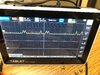
Can you scope TP6 - Try seeing if you get any SSB signal to appear out of L14 - then you may have a dead coil or possibly TR23 is shorted...or something is keeping it on to kill SSB RX


Ok wow we do have similar boards - GREAT.
Ok TP6 is buried in the same place as IC3 - contains your 10.695MHz - just wanted to see if it's getting there...to TR15...


Either D27, C73 or R102 - just need to know if something is going to TR15...
TR23 is right by the R102/C73 mess...
Ok TP6 is buried in the same place as IC3 - contains your 10.695MHz - just wanted to see if it's getting there...to TR15...
Either D27, C73 or R102 - just need to know if something is going to TR15...
TR23 is right by the R102/C73 mess...
What Andy has done is point you to the circuit that has died and killed the SSB receive. The carrier from the 10.695 crystal is needed to get any SSB receive signal. And that oscillator in your radio has no power.
D39 and D40 get checked next. If you show voltage on the anode (no band) end and nothing on the cathode (banded end) that diode is blown. One of them is for USB and the other for LSB. Forgot which is which. Flipping the mode selector from one to the other while probing them would reveal this.
A blown diode would suggest a short to ground in that oscillator circuit. Doesn't still have to be there, could have been caused by a solder bridge that has since been removed. Those diodes just don't have any surge rating at all. Just bridging a foil trace to ground by briefly brushing the tip of a probe across a gap is all it takes.
You'll never guess how I learned that.
73
")
Thanks guys for the awesome help and support and advice and knowledge sharing. I have checked both D39 and D40, D40 stays high all the time regardless of USB/LSB selected. D39 was low on the anode end. I did replace it out but still low. Is there a transistor that's involved in the switch over? TR31 tests fine.
Supplemental TR36/37 are both good.
Further Supplemental TR52 does not have correct voltages.
Supplemental TR36/37 are both good.
Further Supplemental TR52 does not have correct voltages.
Last edited:
Remember you were looking for a tricked cap - now you have a Dead SSB receive.
So in the efforts of all those caps that went in right, Hurray! But - now you have no SSB receive, look back to the "power feed" lines that arrive to specific spots.
Example - TR23, what powers it? A line directly from the S502 switch - the AM line to turn on that transistor.
When you switch in to AM mode - you should see 8 volts on one side of R95, but the other side should be about 0.7 volts - if it is less than that - then there's your short....
So did you check D27? That is a simple diode that is used as an RF switch. It allows some of the RF signal from the 10.695 oscillator - to "gently" mix with - but not drown out - the IF captured off of L14.It mixes in with it at the junction of C72 and C74 - your TP6. It (this TP6) only needs a small mixing "birdie" to sample off of to get enough of the incoming IF Receive to generate the audio being sent to TR16.
If D27 is dead - short - it will kill any signal from TP6 on to the TR15 - because it's PAST the voltage hold back Cap C73, so if a large power carrier surge got into this little area, the Diode is the first to go - any excessive power even from the 10.695 section - will destroy this small signal diode.
Did you try removing TR23 to see if SSB returns in SSB modes. More than likely it won't affect it - but if it does, then the front panel switch may have damaged TR23 - to short out Base to Emitter - sucking down signal and making AM appear all the time - but the radio isn't sending IF to it, because TR23 is a dead short - taking away the SSB signal.
When everything works, TR23 operates only in AM so any signal won't get rectified by D23 / D24 - instead it routes it's IF off of L14 TO TR15 thru C26 - ALSO C24 - SAMPLES this IF and sends it to IC 1 to show on the S/RF meter - which you don't have working in this mode either - so either L14, TR23 or the lines around L14 are faulty.
So to me, everything from L14, D27 - C72, C73, C74 and TR23 are still suspect, because TR15 AND AGC / S/RF meter - need what is there at C72, C74 junction - to even work. D27 needs to have it's Banded end to foil ground - it works as a PIN diode / RF Switch to keep the IF signal (that 10.695MHz) low level - below 0.7 V (may scope to about 1.15 Volts PEP) so it won't drown out the IF trying to get thru to TR15 and IC1
dxChat
- No one is chatting at the moment.