
The recurring question "just because you can does it mean you should?" rears its ugly head once again.
Recent discussions of using the 4-400 tetrode as a grounded-grid triode focus on grounding all the tube's grids.
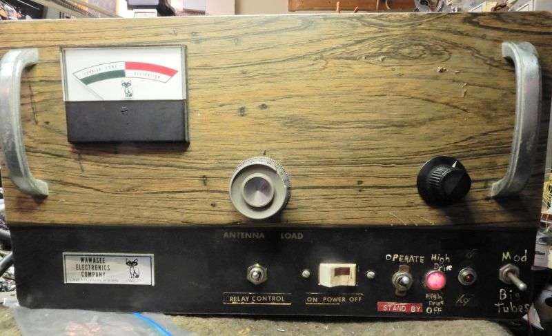
Have a customer that had a supply of 4-400 tubes, but didn't want to buy 3-500Z tubes for a Black Cat JB2000 amplifier.
We tried the ground-all-the-grids method, and the power gain sucked.
Long story short, the tubes' screen grids got a 300-Volt supply cobbled from one of the JB's transformer windings, negative grid bias of about 50 Volts and about 20 Volts of cathode bias from a series string of 30 1N5408 rectifier diodes. The owner wanted it for AM, so biasing the tubes near cutoff kept the anode dissipation at a safer level.
Whew! This setup provided much better power gain.
Until the power transformer blew out.
Oops.
But I'll give the guy credit for being resourceful. He came up with an old custom Peter Dahl HV transformer that had been custom made to run six 572B tubes at around 2000 Volts DC with a full-wave bridge rectifier.
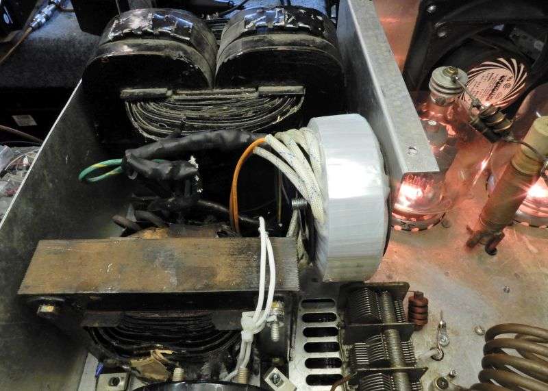
The filament transformer looks like it's been through a house fire, but came from a junked Johnson Thunderbolt amplifier.
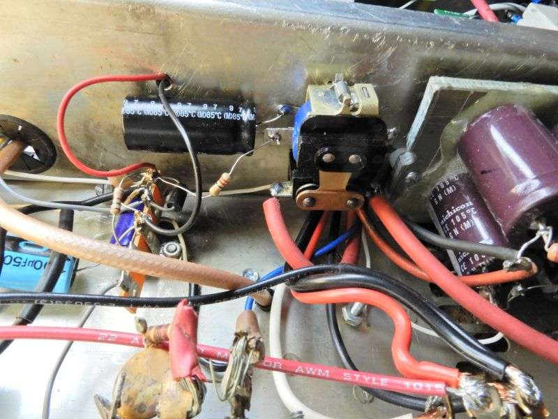
The white doughnut bolted to the center divider comes from Antek to power relays and screen bias.
The HV winding is now connected to a full-wave doubler circuit for just over 4000 Volts to the tubes' plate choke. Drops a bit under load, but this is the max-rated voltage to run this tube.
No, I didn't epoxy these filter caps to this board, but their total rating of 4500 Volts just meets the "90 percent" guideline for operating voltage.
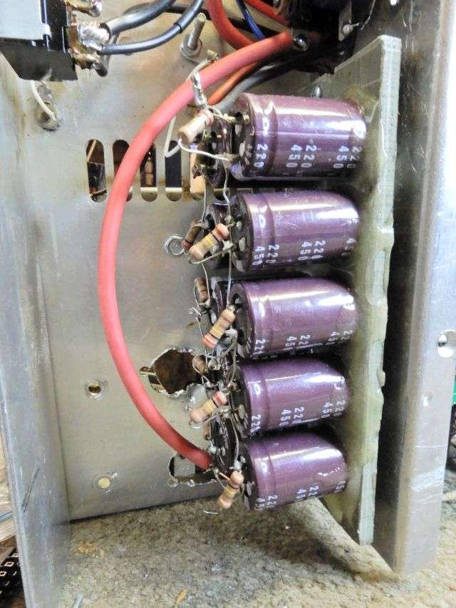
The HV rectifiers and big white surge resistor are mounted half on the top where you see them and half under the board where you can't. Twenty 6-Amp rectifiers should have the surge rating to survive future poof events.
Maybe.
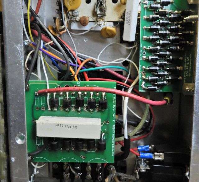
The board full of 3-Amp diodes to the top right is the cathode bias, Thirty diodes gets just over 20 Volts of cathode bias.
The original "soft start" in this amplifier used a single-pole 30-Amp relay between the HV transformer and the doubler circuit. A time delay was meant to let the tiny driver tube warm up before the high voltage goes live.
We used the same-type relay, but powered from the 16 Volts DC that powers the antenna relay. A 22-ohm dropping resistor serves to cut this down to 12 Volts for the relay coil. A 3300 uf capacitor across the coil gets us a turn-on delay of roughly a half second after the power is switched on. Long enough to protect the main power switch.
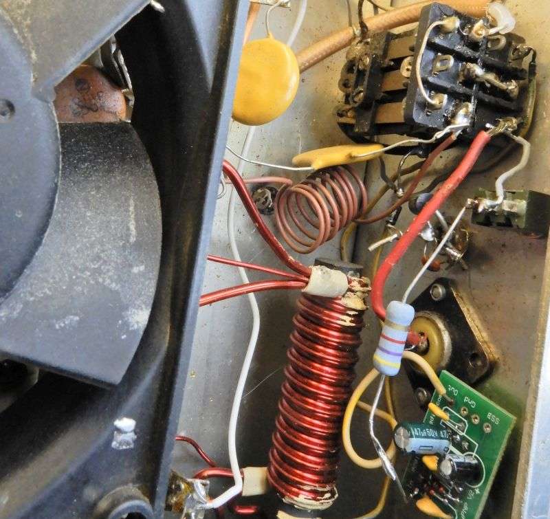
This isn't the most photogenic part of the build, but at the upper left corner is the bridge rectifier and filters for the 350-Volt screen-grid supply. One detail of note here is the the negative side of this supply is not grounded, but connects to the center tap of the filament transformer. This is still technically a grounded-grid amplifier. The source of screen-grid current should be connected between the screen grid and cathode. It would connect to ground only if the tube's cathode is grounded. Not the case here.
Nearer the center of the pic is the half-wave doubler circuit that takes 18 Volts DC to feed a negative 62 Volts (or so) negative fixed bias to the control grids.
Each control grid is grounded by a 1.5k 10-Watt resistor, along with the usual fat ceramic-disc bypass caps.
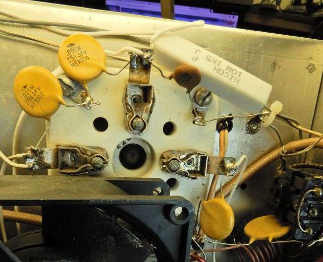
The screen grid on each tube has a 20k 10-Watt return resistor, connected between the screen grid pin of the tube at one end, and the cathode transformer center tap at the other end, same as the screen grid supply.
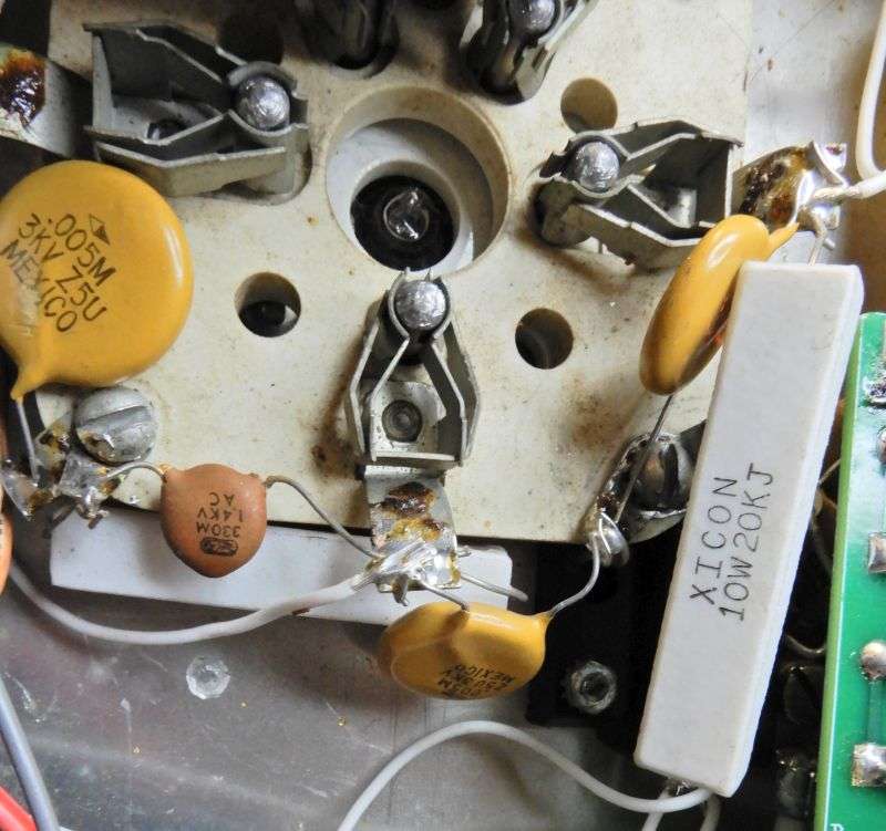
The input-impedance matching to the cathodes uses the small brown coil and two fat 3kv-rated disc caps. Don't want them to puke if a tube flashes over.
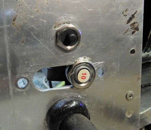
The original 20-Amp breaker is a fire hazard when powered from a 240-Volt circuit. This amp is now 240 only, no 120 option is provided. The small breaker protects the small toroid transformer. The 10-Amp breaker wouldn't.
This setup provides a power gain of about fifteen-to-one. Just goes to show that "The transformer is toast" isn't always a death sentence for a JB2000.
Maybe it should have been.
73
Recent discussions of using the 4-400 tetrode as a grounded-grid triode focus on grounding all the tube's grids.
Have a customer that had a supply of 4-400 tubes, but didn't want to buy 3-500Z tubes for a Black Cat JB2000 amplifier.
We tried the ground-all-the-grids method, and the power gain sucked.
Long story short, the tubes' screen grids got a 300-Volt supply cobbled from one of the JB's transformer windings, negative grid bias of about 50 Volts and about 20 Volts of cathode bias from a series string of 30 1N5408 rectifier diodes. The owner wanted it for AM, so biasing the tubes near cutoff kept the anode dissipation at a safer level.
Whew! This setup provided much better power gain.
Until the power transformer blew out.
Oops.
But I'll give the guy credit for being resourceful. He came up with an old custom Peter Dahl HV transformer that had been custom made to run six 572B tubes at around 2000 Volts DC with a full-wave bridge rectifier.
The filament transformer looks like it's been through a house fire, but came from a junked Johnson Thunderbolt amplifier.
The white doughnut bolted to the center divider comes from Antek to power relays and screen bias.
The HV winding is now connected to a full-wave doubler circuit for just over 4000 Volts to the tubes' plate choke. Drops a bit under load, but this is the max-rated voltage to run this tube.
No, I didn't epoxy these filter caps to this board, but their total rating of 4500 Volts just meets the "90 percent" guideline for operating voltage.
The HV rectifiers and big white surge resistor are mounted half on the top where you see them and half under the board where you can't. Twenty 6-Amp rectifiers should have the surge rating to survive future poof events.
Maybe.
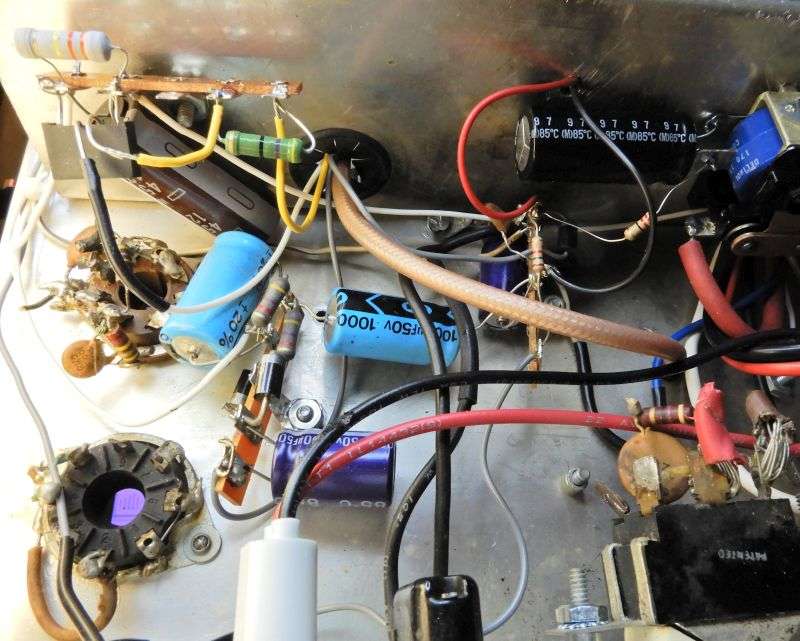
The board full of 3-Amp diodes to the top right is the cathode bias, Thirty diodes gets just over 20 Volts of cathode bias.
The original "soft start" in this amplifier used a single-pole 30-Amp relay between the HV transformer and the doubler circuit. A time delay was meant to let the tiny driver tube warm up before the high voltage goes live.
We used the same-type relay, but powered from the 16 Volts DC that powers the antenna relay. A 22-ohm dropping resistor serves to cut this down to 12 Volts for the relay coil. A 3300 uf capacitor across the coil gets us a turn-on delay of roughly a half second after the power is switched on. Long enough to protect the main power switch.
This isn't the most photogenic part of the build, but at the upper left corner is the bridge rectifier and filters for the 350-Volt screen-grid supply. One detail of note here is the the negative side of this supply is not grounded, but connects to the center tap of the filament transformer. This is still technically a grounded-grid amplifier. The source of screen-grid current should be connected between the screen grid and cathode. It would connect to ground only if the tube's cathode is grounded. Not the case here.
Nearer the center of the pic is the half-wave doubler circuit that takes 18 Volts DC to feed a negative 62 Volts (or so) negative fixed bias to the control grids.
Each control grid is grounded by a 1.5k 10-Watt resistor, along with the usual fat ceramic-disc bypass caps.
The screen grid on each tube has a 20k 10-Watt return resistor, connected between the screen grid pin of the tube at one end, and the cathode transformer center tap at the other end, same as the screen grid supply.
The input-impedance matching to the cathodes uses the small brown coil and two fat 3kv-rated disc caps. Don't want them to puke if a tube flashes over.
The original 20-Amp breaker is a fire hazard when powered from a 240-Volt circuit. This amp is now 240 only, no 120 option is provided. The small breaker protects the small toroid transformer. The 10-Amp breaker wouldn't.
This setup provides a power gain of about fifteen-to-one. Just goes to show that "The transformer is toast" isn't always a death sentence for a JB2000.
Maybe it should have been.
73
