Very good info. Are the 2290 and 2879 easier?I can start a flame fest from this but; It has to be mentioned because of Logistics, Economics - Manufacturing viability - and profitability.
There really is not a lot of differences amongst the MRF line in that package, they all use similar dies, I said SIMILAR - doesn't mean EXACT - so they had to design the die to make it mass production-able.
So that means many of them are nearly identical - expect for substrate - mountings and perhaps a special doping requirement for Mil-Spec operations we simply can't get into...
They are pretty much the same die in the Motorola - Signetics, Thompson and Toshiba and various others, differentiate their dies to enhance layers or aspects of performance for their benefit - but all are the same underneath that cap - only layout and the structure of it is different - but not by much.
So in light of performances between the die layouts - obviously many prefer the ones that are able to perform at twice the values they are rated for.
Well, that's great, but how is that obtained?
Bandwidth mostly.
Note the DUT schematics, all show one way or another the layout equals to the Frequency of Interest - usually the MUF (Maximum Useable Frequency) - so you see their "peaking" or test bench results at the 30MHz - or perhaps the 1MHz if it's needs a type of reproducible disastrous event or SWR measurements to attain their Conjugate values
Narrow the bandwidth, you can then idealize for the MAIN frequency you use it for - so now you know why they tend to "tweak" amps to attain those Gigawatt values Scotty always Save Kirks' Butt from those "Aliens" by having saved some type of power source in some console somewhere...
But I digress...
If you narrow the Bandwidth, you can improve the peak performance to get back some of that lost gain values from their (READ Maker) adaptation to make the Best of a Class C but try to make it Linear.
So review some of the changes in values - the circuit isn't much different, aside from missing the Bias - but look over the PARTS LIST's between and see the changes - they applied many to make the FM-based amp to work in AM - but to ask it to be SSB is possibly asking too much from that design.
Let's keep it simple.
View attachment 41950
This circuit looks VASTLY different than the 455
But study it - note there are similarities in functional "blocks"
They simply put in a tuning "tweak" support to help the end user
develop the proper platform and make the DUT work for their application.
IF you decide to Go cheap, you may have to pay a price on the Pills and their Prescription costs - but if you need to use a Diode - then go ahead, you are simply applying that which is your business to offer some form of Regulation for the Bias supply in the first place. So Temperature compensation would be needed - might as well use it for that purpose - but also know, the DIODE's intrinsic impedance to the flow of power across it's junction is and will be different than Room Temperature.
- R1 isn't 10 ohms - it's 5.6 (5R6) 1/2W
- R2 and R3 are a divider - the VBB is set per your design specs - Diode is your business - they only want the VBB to be able to keep the device in AB mode - if it falls into C - it's only going to produce more IMD and heat - but if your ducks are in a row, it doesn't stay in the "C" Class all the time.
- The VBB setup is unique, you only need to set the CURRENT and note the "breakdown" Base voltage - so you can apply 4 volts (or slightly less) to attain the 50mA drive and leave it alone. If you use the Resistor values specified, and your Bias is less than 4V - you have set the part to drive for SSB mode. (Idle Current)
- If any of you have been paying attention, you don't need tons of AMPS to drive the bias, you should focus more on the input drive levels to make sure you don't cause the "Bias" to bottom out and force the Part into Class C.
- Why This Emphasis on Amps?
- Forcing your part to stay in Class AB, with more amperage
- - will actually PUSH the device into Class A operation
- and with more distortion and power dissipation as the result
- - remember what was said earlier about the RF rectification occurring at the Base of the DUT. It will make the BIAS climb - in this design, you now see why they provided a divider instead of a Diode - you need to drain the RF leaking in, as well as any DC level BIAS that results from the overdriven input. (Your Input Window drive level is key here - too much and BOOM on any device and any platform)
- In keeping the BIAS the same mA effort, your device; when it's exposed to higher levels of RF at the INPUT - will make the device operate more into Class C (Bias starvation) and all it's distortion and power dissipation - but the moment you lower the input values, Bias gets Restored - the admittance works and you obtain your Gain, clean up your signal and get less IMD from your Bias arrangement.
So if you want to COMPENSATE - you may want to add a ZENER in, using a typical Power Regulator using a PNP transistor capable of 2A. You can also physically place the Zener close to the parts - BEFORE R2 - so it arrives to R2/R3 (Divider) as compensated. So include it in the circuit, but not going to ground - instead have it in the VBB Regulator SUPPLYING power to the DUT - like this...
Idle current would only be affected by the Voltage Drop of the Diode back at the Regulator - but thermally using the DUT or heat sink of the amp itself - as the thermal feedback.

You are using an out of date browser. It may not display this or other websites correctly.
You should upgrade or use an alternative browser.
You should upgrade or use an alternative browser.
-
You can now help support WorldwideDX when you shop on Amazon at no additional cost to you! Simply follow this Shop on Amazon link first and a portion of any purchase is sent to WorldwideDX to help with site costs.
-
A Winner has been chosen for the 2026 July 4th Retevis RA89R Giveaway! Click Here to see who won!
Lets talk about amp biasing and building. Bring in the experts.
- Thread starter 025
- Start date
Boy you're lucky I've got time to write these...
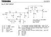
Here's another example of the AB BIAS using the 2879...

There are changes in this one - see the SUBTLE changes in both values and yes, a DIODE...
R1 is now 10 ohms R2 is buffered 2 ohm, R3 is 10 ohm - so the two 10 ohms resistors the buffer Resistor and the Diode - all are used but also run a margin of higher dissipation current that D may not survive easily. Might want to make that a 3A diode for a safety margin.
I mention the 10 ohm resistors because of the divider parses down the current drive - but also allows the DUT to operate linearly because of the very RF effect mentioned earlier - the Base of the DUT will make it's own BIAS - R1 helps the linearity of the current flow from the Rectification.
It's also - CLUE #1 too; on why you see so many amps of different transistor types (Part numbers) using the 10 ohm - because of this very effect - helps with the AM side too. SSB? Not so much...still needs help with this.
So again, the BIAS power requirement is still your business.
Notice too, that they simplified the circuit so you aren't worried too much with parts count, just to make it work - still variable to help you in your platform but simplified to help you see their functional blocks better.
C1 and C2 - variable but act like and RF divider. Something to consider when you build your amp - make an escape route for PEP RF levels that you may not want in the amp. A design like C1 and C2 can help not only with tuning the input, but balancing out the RF PEP levels to idealize the pairing when you make up your Trombone for both Input and Output (your pipes and Choke winds on Ferrite per pair)
Here's another example of the AB BIAS using the 2879...
There are changes in this one - see the SUBTLE changes in both values and yes, a DIODE...
R1 is now 10 ohms R2 is buffered 2 ohm, R3 is 10 ohm - so the two 10 ohms resistors the buffer Resistor and the Diode - all are used but also run a margin of higher dissipation current that D may not survive easily. Might want to make that a 3A diode for a safety margin.
I mention the 10 ohm resistors because of the divider parses down the current drive - but also allows the DUT to operate linearly because of the very RF effect mentioned earlier - the Base of the DUT will make it's own BIAS - R1 helps the linearity of the current flow from the Rectification.
It's also - CLUE #1 too; on why you see so many amps of different transistor types (Part numbers) using the 10 ohm - because of this very effect - helps with the AM side too. SSB? Not so much...still needs help with this.
So again, the BIAS power requirement is still your business.
Notice too, that they simplified the circuit so you aren't worried too much with parts count, just to make it work - still variable to help you in your platform but simplified to help you see their functional blocks better.
C1 and C2 - variable but act like and RF divider. Something to consider when you build your amp - make an escape route for PEP RF levels that you may not want in the amp. A design like C1 and C2 can help not only with tuning the input, but balancing out the RF PEP levels to idealize the pairing when you make up your Trombone for both Input and Output (your pipes and Choke winds on Ferrite per pair)
Attachments

This place has a pretty good selection:Is there a substitute for silver mica caps
They seem hard to get
https://www.tedss.com/Capacitors
Nice.. i think i read somewhere you can use the poly caps?
I am not sure if the poly would have a high enough voltage rating.Nice.. i think i read somewhere you can use the poly caps?
Theres gotta be something else. The blue and orange style are rated like 2kv on some. I know they use the blue ones on tuners that mfj makes but anyway silver mica arent cheap last time i looked so if you dont have a stash of them...I am not sure if the poly would have a high enough voltage rating.
If it works, it works. I always thought there was something about the different types for different applications. Maybe someone can fill us in.Looked up the 500pf 2kv i need for the 80m tank on a amplifier and got a blue one.
View attachment 41973 View attachment 41974
I was under the same impression alsoIf it works, it works. I always thought there was something about the different types for different applications. Maybe someone can fill us in.
I've got one of those, having a member here check it out before I hook it up.......the Hookers sister is sitting on Ebay too....Heres a goofy little amp
The balwin electronics hooker 100.
I dont see the bias circuit here. Some one want to explain this amp and the use of all the electrolytics? Couldn't find a schematic either. View attachment 42054 View attachment 42055 View attachment 42056 View attachment 42057


https://www.ebay.com/itm/BIMBO-100-BILINEAR-/184664729788?_trksid=p2349624.m46890.l49292
I've got one of those, having a member here check it out before I hook it up.......the Hookers sister is sitting on Ebay too....
View attachment 43185they are class c bias
View attachment 43185 View attachment 43188
https://www.ebay.com/itm/BIMBO-100-BILINEAR-/184664729788?_trksid=p2349624.m46890.l49292
dxChat
- No one is chatting at the moment.