
Here is the other half of the lower-channel mod for the Browning Golden Eagle Mark 4A. The receiver this time.
The receiver comes with two tuneable bands and one "fixed" crystal receive frequency. The crystal socket is part of the front-end circuit board. Adding a third tuneable band requires bypassing the fixed-receive hookup on the band selector. Next the third band crystal gets installed alongside the two factory band crystals with its own copy of the transistor-switch circuit.
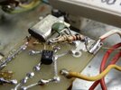
First detail is to bypass the fixed-receive crystal circuit on the band selector. Pretty simple. Unhook two wires leading from the front-end circuit board from the band switch. In this pic it's the white-gray wire soldered to a pad at the pc board's lower-right corner and the white-blue wire along side it.

The gray-white wire just goes away completely.
The blue-white wire gets shortened so it reaches the solder pad that white-gray wire was just removed from. Solder it there.

Now that the fixed-crystal channel feature is disabled we need an additional wire to select the lower-channel band crystal. But it's a tiny bit clumsy. The green wire activates the "CB" band crystal but it's soldered to the "XTL" lug of the selector, along with a tiny bare jumper wire. Both wires get unsoldered from the switch lug.

The green wire now gets lap-soldered to the bare wire. This activates the CB crystal at that switch position only now.

A white wire has been added to the "XTL" lug of the switch where the blue and jumper used to be. The new wire will reach to the crystal board alongside the blue and yellow.
Here's how the band crystals are selected by feeding 11 Volts DC from the band selector for each band. The transistor provides a ground connection to its crystal only when when it has base current.

We just add a transistor, two resistor and a bypass cap to duplicate this function for the lower-channel crystal.
This receiver arrived with a rotary switch added to the rear apron of the chassis. It got removed along with the band crystals it was meant to select. It had a lower-band crystal that gets installed to match the original crystal-switching method.
I'm used to drilling two holes to mount a new lower-channel crystal alongside the other two. This one had short leads and was secured with a small square of VHB adhewive foam. One leg has a 'crutch' wire leading to the "hot" side foil trace where the other two crystals connect.
A cut is made to the front end of the ground foil on this tiny circuit board. It becomes the input pad for the white/red wire we added to the band selector.
The original switch transistor has an odd number. I happen to have equivalent transistors with a quirky house number. Most any RF small-signal transistor will work, like 2N3904, 2N4401, 2SC1674 and a long list of others. The main requirement is a small collector-to-emitter capacitance. Lower-frequency transistors used in audio circits might fail to turn off the crystal. A transistor with too much capacitance will allow the crystal to get its ground connection when the transistor is switched off.
Finding a 22.5 MHz crystal won't be easy. Barkett had them, and Alan Price should make them available when he can. For the moment, it's a turn-over-rocks kind of item.
Now to come up with a way to make the obscure crystal irrelevant.
Soon. Yeah, we always say that.
73[ATTACH type="full" size="800x600"]76353[/ATTACH]
The receiver comes with two tuneable bands and one "fixed" crystal receive frequency. The crystal socket is part of the front-end circuit board. Adding a third tuneable band requires bypassing the fixed-receive hookup on the band selector. Next the third band crystal gets installed alongside the two factory band crystals with its own copy of the transistor-switch circuit.
First detail is to bypass the fixed-receive crystal circuit on the band selector. Pretty simple. Unhook two wires leading from the front-end circuit board from the band switch. In this pic it's the white-gray wire soldered to a pad at the pc board's lower-right corner and the white-blue wire along side it.
The gray-white wire just goes away completely.
The blue-white wire gets shortened so it reaches the solder pad that white-gray wire was just removed from. Solder it there.
Now that the fixed-crystal channel feature is disabled we need an additional wire to select the lower-channel band crystal. But it's a tiny bit clumsy. The green wire activates the "CB" band crystal but it's soldered to the "XTL" lug of the selector, along with a tiny bare jumper wire. Both wires get unsoldered from the switch lug.
The green wire now gets lap-soldered to the bare wire. This activates the CB crystal at that switch position only now.
A white wire has been added to the "XTL" lug of the switch where the blue and jumper used to be. The new wire will reach to the crystal board alongside the blue and yellow.
Here's how the band crystals are selected by feeding 11 Volts DC from the band selector for each band. The transistor provides a ground connection to its crystal only when when it has base current.
We just add a transistor, two resistor and a bypass cap to duplicate this function for the lower-channel crystal.
This receiver arrived with a rotary switch added to the rear apron of the chassis. It got removed along with the band crystals it was meant to select. It had a lower-band crystal that gets installed to match the original crystal-switching method.
I'm used to drilling two holes to mount a new lower-channel crystal alongside the other two. This one had short leads and was secured with a small square of VHB adhewive foam. One leg has a 'crutch' wire leading to the "hot" side foil trace where the other two crystals connect.
A cut is made to the front end of the ground foil on this tiny circuit board. It becomes the input pad for the white/red wire we added to the band selector.
The original switch transistor has an odd number. I happen to have equivalent transistors with a quirky house number. Most any RF small-signal transistor will work, like 2N3904, 2N4401, 2SC1674 and a long list of others. The main requirement is a small collector-to-emitter capacitance. Lower-frequency transistors used in audio circits might fail to turn off the crystal. A transistor with too much capacitance will allow the crystal to get its ground connection when the transistor is switched off.
Finding a 22.5 MHz crystal won't be easy. Barkett had them, and Alan Price should make them available when he can. For the moment, it's a turn-over-rocks kind of item.
Now to come up with a way to make the obscure crystal irrelevant.
Soon. Yeah, we always say that.
73[ATTACH type="full" size="800x600"]76353[/ATTACH]
Attachments
Last edited:
