Today's puttering involves determining how I am going to attach the three 11 foot long, 10 gauge posts into one 33' long segment. This will form the backbone of the mast and will support the rotator and thrust bearing brackets. The pipes have an OD of 2.375" (60.33mm) and an ID of about 2.115" (53.73mm). I want to use a two foot section of aluminum pipe (for weight savings, maybe 0.5" thick wall) at each of the two joints such that there is one foot above and one foot below the junction point. One grade 5, 7/16" bolt will be used at the top and bottom of the joint to connect the mast pipe and inner pipe sleeve together (like I did on my current mast). The closest aluminum pipe I have found to the 53.75mm diameter that would work best for the inner pipe has an OD of 2" (50.8mm). This would leave a bit of slop around the junction pipes. I could possibly find someone with a TIG welder to weld a half-dozen or so filler strips on each of the two sleeves to remove the slack. I also read somewhere else that said just to fill the gap with duct tape. I'm not going to over-engineer this and spend way, way too much money on it for the outcome I expect.

You are using an out of date browser. It may not display this or other websites correctly.
You should upgrade or use an alternative browser.
You should upgrade or use an alternative browser.
-
You can now help support WorldwideDX when you shop on Amazon at no additional cost to you! Simply follow this Shop on Amazon link first and a portion of any purchase is sent to WorldwideDX to help with site costs.
-
A Winner has been chosen for the 2026 July 4th Retevis RA89R Giveaway! Click Here to see who won!
M104C Project
- Thread starter TimmyTheTorch
- Start date
This 2" OD, 0.5" wall, 48" long T6061 aluminum tube may be strong enough to cut in half and use 24" of it in each of the two mast junctions. Kinda pricey though, so I am going to chew on it a bit and try to track down its specs.
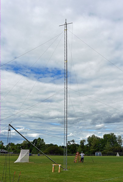
What is it that you are calling a gin pole? I have seen far too many mentions of a "gin pole" in various places lately that are using the term incorrectly. A gin pole is affixed to the side of an existing tower or mast and used to raise/lower antennas etc to mount on that mast or tower. It is also used to build a tower and moves up the side as sections are added. A falling derrick is a separate tower section or mast mounted at a right angle to the main tower or mast and used to more easily tilt it over or stand it up to a vertical position. Just asking because there is far too much misinformation on the internet today, and it seems to be getting much worse as the years go by, and also because I am slightly pedantic.
Falling derrick on the right and gin pole on the left.
Falling derrick on the right and gin pole on the left.

Well, the project is still progressing although not as quickly as I'd like. Life has a way of doing that.
I have collected nearly everything I need to finish the project except for coax, guy wire, another batch of concrete mix, ummm, I'm sure there's more.
I decided to make my own tilting base plate for the mast, have decided on what type I will try to use and got the raw materials. After seeing what was for sale out there and how much some of the better ones would cost, I ended up getting a decent MIG/TIG welder so I can pursue this as a hobby too. I haven't welded anything since high school so it's been awhile.
I have two of the three holes I need dug. I can't dig the third one until I take down the existing mast since the new mast is going up in the same place I have the current one.
A buddy with roofing experience is going to help me install the guy wire anchors on our new roof to minimize the chances of them causing any leaks.
This project can't be done soon enough for me. I am now having an issue I don't recall seeing before. When I have the amp on the high power setting and being driven anything more than maybe 60 percent of its stated input power, when I have the mic keyed the SWR is low for about the first five seconds and then over the next 10 seconds or so creeps up until I unkey the mic (it does not do this with a dummy load). Something is reflecting something somewhere. I have the RF power on the radio set so that the amp dead keys at about 50 watts, which is a lot lower than I was told I should use. I was told 80 watts if using the 2sc2879 transistors or 100 watts using the 2879hg-c transistors I got. The SWR meter is between the amp and antenna. The SWR is nice and low when the amp is off. I doubt there's much difference in my ultimate signal strength pushing out maybe 275 watts at this reduced drive level compared to 400 watts when pushing it harder. I just don't want to damage anything. Taking the antenna down will give me a great chance to go over all the connections I can't currently reach.
Good thing the journey is part of the fun otherwise all of this may be a big PITA.
When I have the amp on the high power setting and being driven anything more than maybe 60 percent of its stated input power, when I have the mic keyed the SWR is low for about the first five seconds and then over the next 10 seconds or so creeps up until I unkey the mic (it does not do this with a dummy load). Something is reflecting something somewhere.
Buy yourself a good line isolator/choke/balun. In the past, I have had that to happen. All the power was not going out the antenna, and the coax was radiating too.
Bought a Palomar Engineers Maxi-Choker 3K that fixed the problem. It was installed about 8.5 feet down below an Imax antenna. Receive noise level went down too. I did not buy the one with the ground lug. I did have to re-tune the antenna after the choke was installed.
I will take a look at that. The balun/choke stuff is still a science I don't quite grasp but as long as it works, I'm game. I do have one smallish ferrite I've been moving around on the coax e.g. right by the radio, outside before the MFJ-272 lightning arrestor and also after it, but no effect was noticed. I've also tried temporarily bypassing the MF2-272 but it did not make a difference.Buy yourself a good line isolator/choke/balun. In the past, I have had that to happen. All the power was not going out the antenna, and the coax was radiating too.
Bought a Palomar Engineers Maxi-Choker 3K that fixed the problem. It was installed about 8.5 feet down below an Imax antenna. Receive noise level went down too. I did not buy the one with the ground lug. I did have to re-tune the antenna after the choke was installed.
It's a shame to remove these shavings created while de-burring the inside of one of the galvanized mast pieces before inserting the sleeve.

Mother Nature showed she can do something similar all by herself.

Mother Nature showed she can do something similar all by herself.
Last edited:
75, I agree with your Choke location on your Imax.Bought a Palomar Engineers Maxi-Choker 3K that fixed the problem. It was installed about 8.5 feet down below an Imax antenna.
I know this is off the subject for this thread, but Timmy was talking about the issues with RF chokes. snippits75 talked about his using a choke 8.5' below his antenna.
Note: some antennas require a different location on the feed line and that is the point I might raise here for further discussion.
Below is my model of the Imax without the mast being isolated, also with and without the choke 8.5"or >...below the bottom of the antenna.
Abbreviations defined in the antenna title.
wC47pF - with Imax capacitor near the middle of the radiator at 47pF.
wC - with CMC choke in the middle of the radiator and is marked with an underscore____.
wTF - with transformer at the base of the radiator for matching.
nRs - with no radials
Attachments
If I end up getting something like a Palomar Engineers MC-1-3000 choke, I'll have to do some experimentation to see if it works best on the radio side or on the antenna side of the MFJ-272 lightning protector (which I have been told should be replaced by an Alpha Delta ATT3G50UHP). Then I'll have to decide if I want to have one inline for each of the M104C and the V58 antenna mounted above it. This equipment list just breeds like rabbits.
Yes CB is constantly buying! But radio is my only hobby, and I enjoy it. Learning about all stuff radio is interesting to me.
Not sure where a good quality choke would be installed on your setup. I just know what worked for me on my antenna system.
Not sure where a good quality choke would be installed on your setup. I just know what worked for me on my antenna system.
Sorry brother snippits, the CMC choke is right below the wire #1 and is 8"-9".Yes CB is constantly buying! But radio is my only hobby, and I enjoy it. Learning about all stuff radio is interesting to me.
Not sure where a good quality choke would be installed on your setup. I just know what worked for me on my antenna system.
In my post above...it was at some point confusing.
The model image of the Imax shown is about 30' to 40' away,,,with you standing on the ground.
Wire #1 is the radiator.
Wire #2 is the 36'mast.
The little red square, a little below the middle of Wire #1, is the 47 ohm capacitor that fixes the Imax pattern. This improves the radiator wire distribution.
The small red circle is the feed point at the bottom of the Imax.
The small bottom red square is the CMC choke that you describe in your post above, and again it is 8"- 9" inches below the feed point for the Imax.
The red lines are indicators of the current distribution and pattern. The currents vary in magnitude as to the distance the current is from the radiator and/or the mast and they are indicated by the current distribution.
Tell me what else you would like to know about this Imax model, or a question that I may be able to answer.
Last edited:
Time for another speed bump. The M104C takes a mast size of 2" OD. That's a good fit for the Yaesu rotor and thrust bearing I have. The M104 is being mounted horizontally and the M58 will be just above it without the ground plane radials. The V58 takes a 1.25" mast so I need to be able to reduce the 2" aluminum mast extending just past the M104C into the 1.25" mast I have in the V58 now (I will be shortening the V58 mast to a foot or two long). I am reasonably sure I have enough various bits and pieces tucked away in my workshop or shed to come up with something.
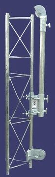
I liked this idea because it will take a lot of stress off the rotor as opposed to directly mounting the rotor on a mast as I done. The company listed in the pic doesn't sell to the U.S. but I found another German company that sells the same item and ships to the U.S. so I purchased them there and they were about 40 EURO'S cheaper for the pair!Sigh, I am going to have some difficulty digging the hole for the tower foundation where I want it. Turns out some buried electrical was re-routed when the window well was dug a few years ago when we finished our basement and it was moved further south along the west wall where I want to put the tower. Oh well. Improvise, adapt, overcome.
To at least get the beam up I may just mount it on a guyed pole. The rotor I have is beefy enough to handle the beam when the rotor is pole-mounted but there's not much safety margin. A local ham showed me this type of rotor mount that still lets you use a guyed pole but the rotor mounts to a plate so it has closer to the tower-mounted strength especially when a second mount is used for a thrust bearing. The guy wires would attach to the pole right below where the rotor bracket is attached. I may just give this a try. Experimenting is a big part of the fun for me, although sometimes my experiments don't exactly go to plan. Live and learn.
View attachment 63360
I just installed the brackets today and I'm very impressed with the workmanship of these brackets. I was concerned about the extra weight because these are plate steel and the thrust bearing adds more too possibly causing my mast to lean but no issues with the mast at all!
I'm using a 21 ft. structural grade 2 inch A500 schedule 80 pipe for the main mast and a 4 ft. 1-1/2 A500 schedule 40 for the rotor mast. This pipe is heavy but rock solid and not likely to fail under stress.
Because the main mast is only 18ft above ground (3 ft is concreted underground), no guy wires are needed as the upper and lower brackets attached to the house studs seem more than sturdy enough.
I would love to have this antenna higher but my neighborhood restrictions say antennas have to be no higher than the roof line and I'm pushing it a bit just above that.
Thanks for posting the pic of those brackets!
Here is a pic of my install

Very nice! That looks very sturdy.I liked this idea because it will take a lot of stress off the rotor as opposed to directly mounting the rotor on a mast as I done. The company listed in the pic doesn't sell to the U.S. but I found another German company that sells the same item and ships to the U.S. so I purchased them there and they were about 40 EURO'S cheaper for the pair!
I just installed the brackets today and I'm very impressed with the workmanship of these brackets. I was concerned about the extra weight because these are plate steel and the thrust bearing adds more too possibly causing my mast to lean but no issues with the mast at all!
I'm using a 21 ft. structural grade 2 inch A500 schedule 80 pipe for the main mast and a 4 ft. 1-1/2 A500 schedule 40 for the rotor mast. This pipe is heavy but rock solid and not likely to fail under stress.
Because the main mast is only 18ft above ground (3 ft is concreted underground), no guy wires are needed as the upper and lower brackets attached to the house studs seem more than sturdy enough.
I would love to have this antenna higher but my neighborhood restrictions say antennas have to be no higher than the roof line and I'm pushing it a bit just above that.
Thanks for posting the pic of those brackets!
Here is a pic of my install
View attachment 63608
I have a mast with an OD of 2-3/8" and need to connect guy wires to it. I am hoping three will suffice but we'll see.
Has anyone come across a guy wire ring like this that will fit a 2-3/8" mast? So for the largest one I can find only goes up to a 2-1/4" mast like the EZ-Up pictured below.
I'm also open to other suggestions on how to connect a guy wire to a mast that does not require drilling holes through the mast. I am hoping to not create additional weak points.
If I can't find one I may just try this one out and replace the eye bolts with longer ones.
dxChat
- No one is chatting at the moment.
