Well, I am slowly but surely making progress. I am making sure to not make this project feel like an unpleasant task so I am taking my time and enjoying other things too. I still need to get the motorcycle out of storage but the weather hasn't been cooperating much lately. It's May 1 and today it is cold and snowing here.
I have a bench mount drill press but had no decent place to keep it. I got tired of moving it around. That sucker is heavy! I knew I was going to need the drill press for multiple things I am doing as part of this project (e.g. making a tilting base plate, anchors, winch plate etc). I had a lot of wood kicking around so I bought a set of casters and built a mobile cart for the press. I already have a 4'x8' table with ramps/casters I built to use for working on snowmobiles, ATV, etc and another 3'x8' with casters I built as a portable work bench. Unfortunately the first version of the drill press table was about 10" too tall so I had to remove this amount from the middle of the legs and sister in shorter legs. Everything is glued and screwed so nothing is going anywhere. It just looks ugly but oh well, at least it's strong and does the job for about $20. Now I could get back to the antenna project.
I have two 12"x12" 1/4" metal plates I am using as the basis for the tilting part. Also two 6" wide metal industrial weld-on hinges that are supposed to each support an 800 pound steel door. I think this should suffice for the weight of the mast, rotor and M104C. The drill press on the new table worked great for drilling the 4 holes I need for the galvanized rods that will be embedded in the concrete.
Oh yes, I also found the right size pipe to use to sleeve the one guy wire anchor pipe. This guy wire pipe is also going to have my youngest daughter's wireless bird feeder camera.
I got the 12' long 2" OD aluminum mast I want to use with the rotor and offset mounts so that's all set.
I completed the mounting plate for the winch. It will be welded between the two heavy duty steel poles that will be used to help raise/lower the mast.
I have brought home 28 60 pound bags of concrete so far. I think I will get another dozen or so to make sure I have enough. I will be renting a portable mixer from Menards and hiring a few neighborhood lads to help with the heavy lifting/mixing. Cheaper than a doctor!
I also found a really good local metal shop for scrap pieces to practice welding as well as use for the real thing. They even gave me a tour of their whole facility. It was a great way to spend my lunch break. I've been back there for more purchases several times since then.
Once the weather improves later this week, the welding will begin. I'm not sure yet if MIG or stick is the way to go. I was told if I go stick to first use a 6011 rod to join the 1/4" metal pieces due to the good penetration then 7018 to basically fill in the rest of the gap. I've done stick welding before but not MIG. I am looking forward to it.
I am getting all of this build stuff out of the way so I can (hopefully) do the concrete, let it set up, then put everything up. I am 100 percent certain it is not going to go this way, but every project needs a goal.

Here's the little table's big brother. I've had the ATV, the buggy, snowmobiles, lawn tractor and more on it over the years. Obviously I love to tinker around with things. Cheaper than a therapist my wife says, plus I usually make a little bit of money on these winter projects.


I have a bench mount drill press but had no decent place to keep it. I got tired of moving it around. That sucker is heavy! I knew I was going to need the drill press for multiple things I am doing as part of this project (e.g. making a tilting base plate, anchors, winch plate etc). I had a lot of wood kicking around so I bought a set of casters and built a mobile cart for the press. I already have a 4'x8' table with ramps/casters I built to use for working on snowmobiles, ATV, etc and another 3'x8' with casters I built as a portable work bench. Unfortunately the first version of the drill press table was about 10" too tall so I had to remove this amount from the middle of the legs and sister in shorter legs. Everything is glued and screwed so nothing is going anywhere. It just looks ugly but oh well, at least it's strong and does the job for about $20. Now I could get back to the antenna project.
I have two 12"x12" 1/4" metal plates I am using as the basis for the tilting part. Also two 6" wide metal industrial weld-on hinges that are supposed to each support an 800 pound steel door. I think this should suffice for the weight of the mast, rotor and M104C. The drill press on the new table worked great for drilling the 4 holes I need for the galvanized rods that will be embedded in the concrete.
Oh yes, I also found the right size pipe to use to sleeve the one guy wire anchor pipe. This guy wire pipe is also going to have my youngest daughter's wireless bird feeder camera.
I got the 12' long 2" OD aluminum mast I want to use with the rotor and offset mounts so that's all set.
I completed the mounting plate for the winch. It will be welded between the two heavy duty steel poles that will be used to help raise/lower the mast.
I have brought home 28 60 pound bags of concrete so far. I think I will get another dozen or so to make sure I have enough. I will be renting a portable mixer from Menards and hiring a few neighborhood lads to help with the heavy lifting/mixing. Cheaper than a doctor!
I also found a really good local metal shop for scrap pieces to practice welding as well as use for the real thing. They even gave me a tour of their whole facility. It was a great way to spend my lunch break. I've been back there for more purchases several times since then.
Once the weather improves later this week, the welding will begin. I'm not sure yet if MIG or stick is the way to go. I was told if I go stick to first use a 6011 rod to join the 1/4" metal pieces due to the good penetration then 7018 to basically fill in the rest of the gap. I've done stick welding before but not MIG. I am looking forward to it.
I am getting all of this build stuff out of the way so I can (hopefully) do the concrete, let it set up, then put everything up. I am 100 percent certain it is not going to go this way, but every project needs a goal.
Here's the little table's big brother. I've had the ATV, the buggy, snowmobiles, lawn tractor and more on it over the years. Obviously I love to tinker around with things. Cheaper than a therapist my wife says, plus I usually make a little bit of money on these winter projects.


")


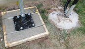
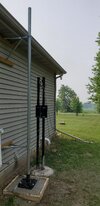


") ) It's the one connecting the bottom and middle sections of 10' long, 2" nominal schedule 40 pipe. The bolts in the picture hold a two foot length of 1.5" nominal schedule 40 pipe inside as a strengthening sleeve. The gap between the OD of the 1.5" nominal and ID of the 2" nominal was taken up by multiple beads welded around the circumference of the sleeve.
) It's the one connecting the bottom and middle sections of 10' long, 2" nominal schedule 40 pipe. The bolts in the picture hold a two foot length of 1.5" nominal schedule 40 pipe inside as a strengthening sleeve. The gap between the OD of the 1.5" nominal and ID of the 2" nominal was taken up by multiple beads welded around the circumference of the sleeve.