Does anyone know where I can get new or used covers for a Maco 750. An older hand that's getting out of cb gave me one, it's reasonably clean inside but some joker decided to re-paint it and make it his own. I need a new meter and covers of anyone knows of anything, I would appreciate it

You are using an out of date browser. It may not display this or other websites correctly.
You should upgrade or use an alternative browser.
You should upgrade or use an alternative browser.
-
You can now help support WorldwideDX when you shop on Amazon at no additional cost to you! Simply follow this Shop on Amazon link first and a portion of any purchase is sent to WorldwideDX to help with site costs.
-
A Winner has been chosen for the 2026 July 4th Retevis RA89R Giveaway! Click Here to see who won!
Maco 750 skins
- Thread starter dozerman
- Start date
And a keying circuit. The guy that converted this box to 6 volt, made a keying circuit, that to me, looks sketchy at best. The amp won't key up after replacing every diode, resistor, capacitor and transistor. Does anyone make a circuit that is "plug and play"?
I doubt anyone makes a keying circuit have you seen how shotty factory keying circuits for a lot of CB linears look? Let's just say they are no better than the receive amp in them.
If it is just a paint issue get hold of some aircraft remover or sandblast them. Then start over! If you know what your doing you can give it a nice paint job with spray paint. 99% of people have no clue how to use spray paint.
If you look online you should be able to find a schematic and reproduce the factory keying circuit. Did you replace or check the cap for the relay? Did you check the relays operation separately?
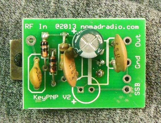
Here's what we have been using for decades. Got tired of hand wiring the parts and 'flying' them on the transistor's leads. The pc board does reduce the labor to build them.
A resistor goes from the "RF In" hole to the center pin of the amplifier's input socket. Low drive levels call for a 2.2k 2 Watt resistor. A 4.7k 2 Watt is okay up to around 200 Watt peaks.
The cold side of the relay coil goes to the "Out" hole. The transistor tab just bolts to the chassis for the ground connection. This assumes a positive DC voltage on the relay. Older boxes that use a negative DC voltage to run the relay require that the thing be mounted with the transistor tab isolated from ground and the "out" side grounded. The "Gnd" side would then go to the cold side of the relay coil.

Just one problem. It's too cheap to sell one at a time. My overhead to make a sale transaction is about equal to what we sell it for on a customer's repair bill.
But I'll make you a proposition. Mail me 15 bucks and I'll pack one into an envelope and send it to you.
We're at:
Nomad Radio
1615 Bardstown Road
Louisville, KY 40205
The snail-mail addy is on our web site, too.\
Thought about putting them on Ebay, but a price high enough to cover the overhead would make it at least thirty bucks. Just doesn't seem worth that much.
Not a big deal to build. Found a schemo on file.
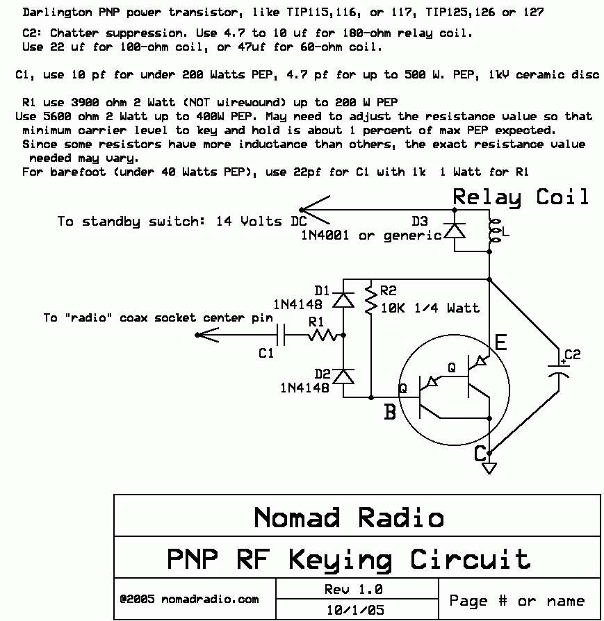
Works every time.
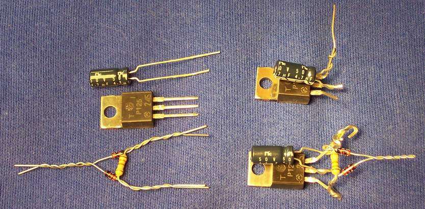
(edit) Found a pic showing the steps to just "twist" one up the old way.
73
A resistor goes from the "RF In" hole to the center pin of the amplifier's input socket. Low drive levels call for a 2.2k 2 Watt resistor. A 4.7k 2 Watt is okay up to around 200 Watt peaks.
The cold side of the relay coil goes to the "Out" hole. The transistor tab just bolts to the chassis for the ground connection. This assumes a positive DC voltage on the relay. Older boxes that use a negative DC voltage to run the relay require that the thing be mounted with the transistor tab isolated from ground and the "out" side grounded. The "Gnd" side would then go to the cold side of the relay coil.
Just one problem. It's too cheap to sell one at a time. My overhead to make a sale transaction is about equal to what we sell it for on a customer's repair bill.
But I'll make you a proposition. Mail me 15 bucks and I'll pack one into an envelope and send it to you.
We're at:
Nomad Radio
1615 Bardstown Road
Louisville, KY 40205
The snail-mail addy is on our web site, too.\
Thought about putting them on Ebay, but a price high enough to cover the overhead would make it at least thirty bucks. Just doesn't seem worth that much.
Not a big deal to build. Found a schemo on file.
Works every time.
(edit) Found a pic showing the steps to just "twist" one up the old way.
73
Last edited:
I doubt anyone makes a keying circuit have you seen how shotty factory keying circuits for a lot of CB linears look? Let's just say they are no better than the receive amp in them.
If it is just a paint issue get hold of some aircraft remover or sandblast them. Then start over! If you know what your doing you can give it a nice paint job with spray paint. 99% of people have no clue how to use spray paint.
If you look online you should be able to find a schematic and reproduce the factory keying circuit. Did you replace or check the cap for the relay? Did you check the relays operation separately?
Well it's not just a matter of paint. They took and cut the sides off and put new sides on that are louvered. Just looks nasty the way it's done. Since posting this, I bought another 750 for parts. Has potential to be restored for sure. But it's gonna be a parts rig. Has good tuners, transformers, fan and such. No tubes tho. And this one had a "schetchy" keying circuit as well lol after trying several different transistors, I've got it keying they way it should.
Here's what we have been using for decades. Got tired of hand wiring the parts and 'flying' them on the transistor's leads. The pc board does reduce the labor to build them.
A resistor goes from the "RF In" hole to the center pin of the amplifier's input socket. Low drive levels call for a 2.2k 2 Watt resistor. A 4.7k 2 Watt is okay up to around 200 Watt peaks.
The cold side of the relay coil goes to the "Out" hole. The transistor tab just bolts to the chassis for the ground connection. This assumes a positive DC voltage on the relay. Older boxes that use a negative DC voltage to run the relay require that the thing be mounted with the transistor tab isolated from ground and the "out" side grounded. The "Gnd" side would then go to the cold side of the relay coil.
Just one problem. It's too cheap to sell one at a time. My overhead to make a sale transaction is about equal to what we sell it for on a customer's repair bill.
But I'll make you a proposition. Mail me 15 bucks and I'll pack one into an envelope and send it to you.
We're at:
Nomad Radio
1615 Bardstown Road
Louisville, KY 40205
The snail-mail addy is on our web site, too.\
Thought about putting them on Ebay, but a price high enough to cover the overhead would make it at least thirty bucks. Just doesn't seem worth that much.
Not a big deal to build. Found a schemo on file.
Works every time.
(edit) Found a pic showing the steps to just "twist" one up the old way.
73
I will gladly buy a couple of them. How do you want the money?
Also, I forgot to mention in the last reply, once I got it keyed up and went to tune the amp, I had zero output. No biggie, didn't figure the tubes were any good. I put two strong 6LB6's in for the drivers and was about to start tuning. I can get 30 watt dk and 100 pep BUT the entire time, the modulation meter quivers from 0-100%. On air it sounds like a machine gun at 100% and an old John Deere put put tractor around 0%. Lol what I'm the world causes that?? Noisy tubes??
Well just put in 8 strong 6LB6's in and it does the same thing. Time to flip it back over I guess
dxChat
- No one is chatting at the moment.