• You can now help support WorldwideDX when you shop on Amazon at no additional cost to you! Simply follow this Shop on Amazon link first and a portion of any purchase is sent to WorldwideDX to help with site costs.

Magnum 257HP Power Adjustment

buickid

304 'round the minigrass
Nov 22, 2012
228
134
53
Kona, Hawaii
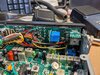
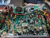
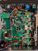
Have a 257HP that does 1.8 or so watts with the variable all the way down, and a hair under 18w with the variable all the way up. I thought the high was a bit too much, so I looked inside and the VR that controls that was all the way down to the stop already. Turning it the other way indeed made it go up. What's the deal here, is the RFX giving too much gain? Same with FM, just under 18w.

Would like to dial the low power down to 1-1.5w as well, but not sure what controls that. CB Tricks has a adjustment diagram, but it appears slightly different than my radio, and low power has two adjustments. Is there a service manual that lists the alignment procedure? RFX75 seems to get very hot fairly quick during testing, another reason to want to dial the power back some.

Love this radio but documentation seems to be lacking, guess Sam Lewis was secretive?

Thanks!
 

Magnum/RF Limited, Hmm - two Great Companies that - well, didn't get along very well at the start of their relationship.

Sounds like you have their Hybridized version of a later set - so if you want help, we'll need to know the board to help you find and fix the tuning problem.

The Power reduction section on that radio is a variant of a Galaxy-based design. And later designs refined it before they abandoned the chassis and went in another direction once they had their differences settled.
Original 257 Design...
upload_2020-11-13_8-35-54.png

Be lucky you have the ERF7530's still working - many operators burn these things up. You have a keeper - but if you're splitting hairs over 1.8 versus 1.5 Watts - Why? You're getting into a region of bias control that WILL burn those ERF7530's up...

These are SMD disasters - they work UNTOUCHED, the moment a hot soldering iron gets in there - its like unleashing a Bull in a China shop - CRASH - BANG - POP - poof...
 
Last edited:
  • Like
Reactions: NZ8N and nickr
Output for that radio will be around 60-70 watts. You'll see output drop a bit when the RFX gets hot. I'd probably set it to key at 10 watts and swing from there even if the peak was only 50 watts.

Those radios get hot so better not to push them to maximum and they'll last a lot longer.
 
Sounds like you have their Hybridized version of a later set - so if you want help, we'll need to know the board to help you find and fix the tuning problem.

Be lucky you have the ERF7530's still working - many operators burn these things up. You have a keeper - but if you're splitting hairs over 1.8 versus 1.5 Watts - Why? You're getting into a region of bias control that WILL burn those ERF7530's up...​

These are SMD disasters - they work UNTOUCHED, the moment a hot soldering iron gets in there - its like unleashing a Bull in a China shop - CRASH - BANG - POP - poof...

Definitely not trying to squeeze every last watt out of this thing, 1.8W doesn't bother me so much I guess, more so the high power side of things. I've attached some pictures of the board, since I don't see any obvious other markings, though they might be hiding under the various boards bolted to the chassis. Thank you for your reply, always very thoughtfully written.

Output for that radio will be around 60-70 watts. You'll see output drop a bit when the RFX gets hot. I'd probably set it to key at 10 watts and swing from there even if the peak was only 50 watts.

Those radios get hot so better not to push them to maximum and they'll last a lot longer.


Definitely gets hot, that's for sure. That's why I want to get everything straightened out, to try and keep the heat down. This radio belonged to a very good friend who went SK, so I'm trying to keep it in top shape!

Buickid, there are usually a low and a hi trimmer pot for radio's with variable RF power. I think it involves a process of adjusting both so they play well together. This link is for the regular 257 but the pot numbers might be the same.

http://www.cbtricks.com/radios/rflimited/magnum_257/257_tx_adj.htm

Unfortunately my radio seems quite a bit different from the original 257, hopefully someone has worked on these newer 257s! This one is even missing one of the VRs pictured in CB Trick's newer adjustment diagram
 

Attachments

  • IMG_20201113_141041.jpg
    IMG_20201113_141041.jpg
    2.5 MB · Views: 25
  • IMG_20201113_141006.jpg
    IMG_20201113_141006.jpg
    2.5 MB · Views: 27
  • IMG_20201113_140928.jpg
    IMG_20201113_140928.jpg
    2.4 MB · Views: 27
No, been busy with A LOT of things going on around here...

Welcome to the WEEKS before the Holidays...

XYL's caught up in it - so we've been busy...:)
 
  • Like
Reactions: buickid
@Handy Andy did you take a peek at the pictures of the board by chance?

So don't quote me on this as it's been 8-9 years since I've had a 257 of any type in front of me. The original 257 and Roadpro had similar adjustment points and I've pretty sure on the 257HP the AM power adjustment was in the same spot.

This info is really "at your own risk" as it's been years and without having the radio in front of me I'm not 100%.

In this old video you can see RV16 location for AM power adjustment on a Titan Roadpro II which used the same boards as the 257 -

I'm starting to recall there wasn't a hi/lo adjustment on the Magnum 257's? Perhaps one of our resident tech's can pipe in on that.

Anyway - if you look at the images at the end of this review - http://cbradiomagazine.com/magnum-257hp-10-meter-am-fm-ssb-export-review/
you'll see the layout of the board is still the same on the 257HP as the older radios for the most part. One of the pots on mine is a different type than yours but I had an early model at the time from Sam.

If you compare the Roadpro video location for AM power to the photos at the bottom of the review you should be able to figure out the AM power adjustment.

Now if there isn't a low power / hi power adjustment like many radios, turning down the AM power will likely effect deadkey and peak. The RFX75 on the 257 is a sensitive beast though so I'm not sure what happens during that adjustment. I know I did tuning on the one in the review but it's just been so many years and so many radios later I can't remember exact details so I apologize.

I'd wait for confirmation from some other members before messing with anything.
 
I'm with @Big Kahuna on this - thanks for your input on this - it helps!

Got anything on pics of the RF Amp board?

Wanted to warn you that the output of the TX strip is FIXED output - several stages upstream.

(The RED BOX etc stuff I posted)

So you don't have more than a stage or two to even "adjust" power levels to begin a transition from the low-level pre-amp signal you have - to the new level of signal.
  • What I speak of here is the changes to the amp stages to "nudge" the signal lower, or even provide a greater window of adjustment - this radio doesn't mess with a dual stage Driver, Final combo - to an amp of a fixed gain. The end of the line - is the twin pairing of the 7530 - which it FEEDS from the AM regulator.
  • The AM Regulator adjusts the carrier bias as well as the "mid point" for the audio envelope - I'm saying that so you are aware that this radio is designed to keep symmetry the AM regulator.
    • that Regulator has to dissipate several Amperes of current LINEARLY to make this radio work.
    • You are using MOSFET's in the output, biased to operate somewhat more linearly than they are designed for.
    • To lower the wattage - you have few choices and none of them pose any true benefit....
    • Detune the TX strip to more closely match the expected power at low wattage
      • Reducing the overall amount of wattage PEP and RMS/AVG - just to meet your 1.5 watt needs...
    • Replace/Swap the Driver with a Bipolar part (1969) to reduce output drive level of the DRIVER stage to the FINAL-paring to achieve the reduced wattage...
      • Again, this places the radio is a less than ideal position and results in a lowered performance curve of PEP and power.
        • The increased danger of rework to change the bias scheme from the MOSFET style to the traditional Bipolar (AB2) design - requires considerable rework and part swaps - not a simple drop in.
  • The Key Word here, is each stage has a FIXED gain to it.
    • And only the last two stages takes in (has applied) the audio Drive and BIAS - so your variability is only at that point.
    • IN the Discrete world we'd try to modify the preceding stage (see above DETUNE)
  • You can change this level of gain to offset one parameter or add another level of variability but you're stuck with the TGECHNOLOGY it has on board already - you don't have a lot of choices.
  • A "last ditch effort" is to apply NFB to the Pre-Driver - your 2314 - located in the above photo Q74
upload_2020-11-24_15-40-40.png
C281's value is increased to reduce gain output of a
Pre-Driver stage to lessen gain further downstream.
You already have something there - it's simply not enough
This too - affects GAIN and PEP.
The ways to fix that require some minor work, and as I said before these are SMD nightmares for the typical hobbyist or even more experienced techs alike...they are compact and swarming with obstacles like the IF and RF cans - so the effort may not be worth the liability to do this.

Your best approach is to;
  • Adjust AM power, ALC and AMC controls to find a working level of power curve.
  • Add a RF shunt to the AMP you're putting this into to lessen your power curve,
    • This is a "blunt force" Temporary fix, approach to fixing this problem
  • Detune AM power - in doing so will affect how ALC and AMC react - which may not be enough.
Christmas is close by...
upload_2020-11-24_15-25-55.png
Give yourself another gift... get another radio - it may be the better and more cost efficient approach to this.

EDIT: Oh good grief! Meant Big Kahuna - Sorry...
 
Last edited:
@Big Kahuna and @Handy Andy, I appreciate both of your expert inputs on this issue. Although I may not always understand everything, I never fail to learn something new from your posts. I guess I'll leave the radio the way it is, and just be judicious on the use of the RF Power control, keeping it down if I plan to get long winded (not often).

Seeing as the AM Power pot is already all the way down, I guess there's not much in the way of easy adjustment that will bring the dead key down to 15W from 18W with the RF Power all the way up. The radio works fine as is, I just wanted to make it a little more "fool proof" if there was an easy way to do so, keep it from getting so hot. Sounds like this radio was a great idea, executed in a slightly less than ideal manner, maybe due to space or budgetary constraints.

This was the radio of a very good friend who is SK now, so I don't plan on beating it up, I've got a bunch of other radios for that. Picked up a 2510 in decent shape, plan on recapping it and sending it to the 2510 guru for an alignment, and got a beater S45 that will be off to Superior CB for a new channel selector. Will pick one of those to run in the mobile behind an old Toshiba powered DX500V. Have a barefoot 979 in there that I'm having fun with right now.

Thanks again, and have a great Thanksgiving!
 
  • Like
Reactions: Handy Andy
Sounds like you've got the right idea. The first 257HP's were hit or miss with issues. I know a couple of people that had no issues and a couple of people that had to send them back to have them adjusted. They were one of the more finicky models produced because they were one of the earlier models to have the RFX75 added and I think they were still figuring that out. It's a good radio I just wouldn't mess with it if it working fine. Use that variable power to turn it down and keep it cool and have fun. Best wishes.
 
  • Like
Reactions: buickid
Reminds me of the EAGLE and Sidewinder 400 - TRS-485 - all with those backlit control rings.

The 15W to 18W - also worked on the 12V versus the 13.8 ~ 14.4V most vehicles and power supplies run now.

So you may be seeing that wattage boost due to the rise in voltage.

The 3pF - you can do up a little something for it- but then too, the hot soldering iron trying to get at that chip cap can ruin the radio

Fun radios - but got hot under mobile use.

If yours still works - remember your friend got it from a place during those eras of "We got away with this - so let's try this" approach from the different "offshoots" of the bigger 3 Cobra/Uniden/Midland-ALAN - these smaller "production runs" were a great learning tool and fun little packages for those that needed an Exotic but nothing too complex - CB radio with Funnies and the modes most wanted.

They weren't stellar in performance only with power levels of - well, - er - eh? (Read as not much as stand alones, but did well with amps behind them they could drive) and really didn't have a big market for toys and mics for these offshoots - but they were fun to use.

Just run it knowing; The lower the wattage the lesser they heated up and the longer they lasted.
 
  • Like
Reactions: buickid
@Big Kahuna Seems like there's a story to be told about RF Limited/Magnum (and others) that few know about unless they were there, with some sort of roots in the industry. Wish it was published or otherwise available to read about. Sounds like it was an interesting time, sort of a peak, when companies were still actively developing new radios or at least truly revising older ones, taking advantage of technology that had become more economical (SMT, MSOFETs, etc). Now we just have 31 different flavors of the same ol radio, the "new releases" are the same thing from the past decade with blue LEDs (does anyone else hate how everything is blue now? I want to have my 979 changed back to a white meter light, green ch display, and red/green TX/RX LED), or maybe one of the Ranger N2/3/4 amp strapped to the bottom.

@Handy Andy Forgot about the higher-than-12V factor from the mobile/power supply, that could very well do it also. I think I'll leave well enough alone before I break something, and let the ol' gal cruise along as a memory of good times. Got a couple S45HP from the same friend that have some small issues I need to get taken care of also...
 
  • Like
Reactions: Handy Andy
The Sam Lewis story is a great one, he was an interesting guy to talk to. His son now runs the company (Magnum/Palomar/RF Limited).

https://www.palomarelectronics.com/ this is the current company.
Is there any real activity from them? I know there was talk of bringing the Palomar name back to greatness, but I haven't heard anything in a while, beside them selling some transistors.
 

dxChat
Help Users
  • No one is chatting at the moment.
  • dxBot:
    Tucker442 has left the room.
  • @ BJ radionut:
    LIVE 10:00 AM EST :cool:
  • @ Charles Edwards:
    I'm looking for factory settings 1 through 59 for a AT 5555 n2 or AT500 M2 I only wrote down half the values feel like a idiot I need help will be appreciated