
You are using an out of date browser. It may not display this or other websites correctly.
You should upgrade or use an alternative browser.
You should upgrade or use an alternative browser.
-
You can now help support WorldwideDX when you shop on Amazon at no additional cost to you! Simply follow this Shop on Amazon link first and a portion of any purchase is sent to WorldwideDX to help with site costs.
-
A Winner has been chosen for the 2026 July 4th Retevis RA89R Giveaway! Click Here to see who won!
Marconi comparing New Top One vs. Old Top One
- Thread starter Marconi
- Start date
Marconi, have you ever thought of becoming a ham? With what you know you would have fun experimenting with antennas!
Well I'm too old now, but most of my real life buddies were all ham operators. I could never bring myself to get that interested. Most are all gone now. I really only enjoy discussing antennas, and I don't even radio much anymore.
Radio has always been an on-again, off-again deal with me.
Thanks for your comment though.
This is true, I did not have my Imax set up with a ground plane at all, only a choke with good rg213.
Tuner, I was posting something about the AstroPlane/NTO on another forum and in my checking the Avanti Manual, I noted a caution for guying the original model. It stated that the minimum separation clearance for non conductive guy lines should be at least 4' feet below the hoop. I see your guy setup is above the hoop. I don't know if or what difference that might make, but it is worth noting. All I know is the bottom of the A/P's hoop is very large, like 30" in diameter, compared to the wavelength, and thus the hoop has a very heavy voltage field in the base area of this antenna. Maybe this is why Avanti gave such a warning about that area. Testing this would be the only way to know for sure though.
The Imax has a key flaw that makes it hard for me to determine if the 1/4 wave ground plane has any signal to noise ratio advantage or if the Imax was not a good comparison.
Shockwave, I don't know the answer to this situation either. It seems to me I've always noted a bit more noise on my A99/Imax, so it might not be a good comparison as you note. I think Tuner was just reporting what he noticed as a practical matter.
I have never worked my Imax with a GPK, but I've heard plenty of similar reports to the A99 with a GPK, and that being the GPK makes little performance differences that can be detected just using a radio.
That is coax radiation. Without a full set of 1/4 wavelength radials at the feedpoint (short GPK doesn't count) we cannot decouple the coax from the antenna properly. It then becomes part of the antenna. That's not just in transmit causing RFI either. It's in receive too. Allowing the path your coax takes to pickup any type of electrical or RF interference before reaching the receiver. The 5/8 wave ground plane would be a more interesting comparison with signal to noise.
I've also heard you remark countless times that the Imax/A99 were designed to work without a GPK, and I agree. I thought that was just your way of noting why we were seeing little on no difference in their using a GPK. Now you're telling us the short GPK does not count, suggesting that only full 1/4 wave radials will make a difference, and it being the only way we can decouple the coax from the antenna properly. Which is it?
Two points in my thinking.
One is I see plenty of reports suggesting they have currents on the mast and/or feed lines using other antennas, and some note they have 1/4 wave radials. So, something else is apparently creating such problems besides the lack of radials. I'll also note that in my modeling I see a huge difference in the currents flowing on the mast at different heights sometimes...using the same antenna. No body ever mentions antenna height when complaining of common mode currents or TVI problems, and I never thought about height in this regard until I started modeling. What if height might be playing a big part in mitigating these mast/feedline currents at times. Could this also be why we don't hear everybody complaining about such currents, because they were just lucky with the height of their antenna? Just a thought!
Two, is that I've connected my VA1 analyzer directly to both my Imax/A99 and it shows little to no difference in the match compared to when using a tuned 1/2 wavelength feed line. I would think if there were heavy currents flowing on the feed line, it would tend to affect the match somewhat. I don't have the answers either, but I tend to believe the ideas presented by Steve Yates, AA5TB, on his report on EFHW antennas: AA5TB - The End Fed Half Wave Antenna
His idea suggests to me that the EFHW only requires about .05 wavelength of counterpoise current return path for effectively radiating an end fed 1/2 wave wire, and that adding a radial makes little noticeable difference. Maybe this is what Solarcon accomplishes in their A99 and Imax.
My old radio mentor buddy always use to tell me to keep my antenna feed lines at a random length compared to the wavelength for some reason, and use to use 45' - 50' feet for 11 meters most of the time.
I've said the following for years,
Marconi said:...that there appears to me to be very little current flowing at the end of a 1/2 wave...for a ground plan radial to work with. At this end point on the 1/2 wave the voltage is at its peak, and current is at its minimum, so where does the necessary current come from that flows into (allows) the radial to work?
A 5/8 wave may be a little different, because there is a bit of current flowing at its base, but it should be minimal.
One interesting aspect here is that a good antenna can prevent poor quality coax from radiating and picking up undesired signals in receive but a poor antenna can allow the best coax to radiate and pickup undesired signals.
Shockwave, give me an example of a good antenna that can prevent coax from radiating, I would like to make a model of it, and see if height will effect the currents on the mast like my other models show.
The EFHW I've brewed work with or without GP radials, too.
In my experiment with the EFHW a while back Marconi and I put this idea through the paces to see whether there was detectable differences. That episode is recorded in the EFHW thread from some time lastr SPring, I believe. I ended up with the notion that the fine tuning I put into the antennas resulted in a very good EFHW using the radials. I was impressed.
I run one of them now over my 4el Yagi. It is choked and I depend on the Yagi to provide a kind of GP effect. It is pretty quiet where it is, and works well. I do not detect either TVI nor CMC with it in my PC speakers. The vintage TV is gone so I can not use it to test for TVI.
The EFHW I've brewed work with or without GP radials, too.
In my experiment with the EFHW a while back Marconi and I put this idea through the paces to see whether there was detectable differences. That episode is recorded in the EFHW thread from some time lastr SPring, I believe. I ended up with the notion that the fine tuning I put into the antennas resulted in a very good EFHW using the radials. I was impressed.
I run one of them now over my 4el Yagi. It is choked and I depend on the Yagi to provide a kind of GP effect. It is pretty quiet where it is, and works well. I do not detect either TVI nor CMC with it in my PC speakers. The vintage TV is gone so I can not use it to test for TVI.
Homer, do you remember when working with your radials...what length and angle worked best?
I'm working on a Eznec modeling idea for a thread to try and show what I see regarding the effects of height and feedline length on the likelihood of TVI and pattern skewing...due to common mode currents. We know that the magnitude of common mode currents is determined by a lack of balance in the currents at the feed point, but I think that height has a primary effect on this magnitude.
I'll start by using an elevated horizontal center fed dipole model at two heights, 36' feet and 40.5' feet. I hope this model will show how I evaluate the currents as bad or not, and thus indicate if TVI is likely or not with a simple change in height. This is just an idea, but I would like some input.
I've also made a 5/8 wave model with 4 x 1/4 wave horizontal radials, but I'm considering to do a version with slanted down radials...if you found they worked best for you on your end fed 1/2 wave.
horizontal -
What I ended up using was the set of radials I had previously made for another antenna. They had six x 3' radials and six x 5' radials - 12 in all.
What I ended up using was the set of radials I had previously made for another antenna. They had six x 3' radials and six x 5' radials - 12 in all.
Homer, do you remember when working with your radials...what length and angle worked best?
I'm working on a Eznec modeling idea for a thread to try and show what I see regarding the effects of height and feedline length on the likelihood of TVI and pattern skewing...due to common mode currents. We know that the magnitude of common mode currents is determined by a lack of balance in the currents at the feed point, but I think that height has a primary effect on this magnitude.
I'll start by using an elevated horizontal center fed dipole model at two heights, 36' feet and 40.5' feet. I hope this model will show how I evaluate the currents as bad or not, and thus indicate if TVI is likely or not with a simple change in height. This is just an idea, but I would like some input.
I've also made a 5/8 wave model with 4 x 1/4 wave horizontal radials, but I'm considering to do a version with slanted down radials...if you found they worked best for you on your end fed 1/2 wave.
Antenna height will affect the magnitude of the common-mode currents, as a result of increasing feed-line loss.
Hi Marconi,
i have always watched & enjoyed your antenna reviews on youtube & appreciate what you do & sharing your reviews with us all, & with the reviews sirio has done a great job with creating the top one as many people seem to be pleased with there performance for a shorter home base antenna specially for those who are unable to have a tall antenna at there QTH.
i have always watched & enjoyed your antenna reviews on youtube & appreciate what you do & sharing your reviews with us all, & with the reviews sirio has done a great job with creating the top one as many people seem to be pleased with there performance for a shorter home base antenna specially for those who are unable to have a tall antenna at there QTH.
Antenna height will affect the magnitude of the common-mode currents, as a result of increasing feed-line loss.
N5IT, I agree such losses do have an effect.
I just recently posted a new thread about an idea on CMC's and antenna height (feed line length) in the antenna section.
Hi Marconi,
i have always watched & enjoyed your antenna reviews on youtube & appreciate what you do & sharing your reviews with us all, & with the reviews sirio has done a great job with creating the top one as many people seem to be pleased with there performance for a shorter home base antenna specially for those who are unable to have a tall antenna at there QTH.
Thanks for the nice comments Wild Fire.
IMO the A/P was always unappreciated and I felt it was mainly from guys that probably never owned one, and though it only worked well when it was mounted low to the Earth...copying comments they had overheard.
Now it looks like a little of the same is probably true about the New Top One, but this time we just don't hear many comments, like no body was buying it, and maybe that was because it was too short or due to the bad publicity about the AstroPlane.
Personally, I was amazed with the results when I first installed my NTO. When I got it, I was a little confused with the instructions not having many dimensions, but when I put it together I realized it was like plug and play.
I was also impressed with the match right of of the box. The first time I built it...it showed me an almost perfect SWR match, and a very large bandwidth right where I set it from the frequency instructions.
I noticed your cmc thread and will certainly check it out. I have currently been reading thru the 44+ pages of the New Sirio Gain Master thread. Last night I got side tracked by Booty Monsters old Sigma IV thread, which led to a very lengthy thread on eham. I've known about some of this material for a while now, but finally getting around to enjoying it. 73
i would never think about getting a fiberglass antenna as i have read & seen pictures of fiberglass antennas after they have been hit with lightning from thunderstorms as fiberglass antenna`s seem to attract lightning & well not much left afterwards as fiberglass ends up having splinters & the coil burnt out inside the antenna 
but i guess to protect the radio from getting hit with the lightning i thought everybody knew to unplug the coax from the radio to the antenna while there is a thunderstorm near there location,
but even smaller antenna`s like the sirio boomerang can do a good 20 30 miles on FM & does pretty well in to Europe on 10 meters & i did read some where that a guy in California while using a boomerang made a contact in to Florida.
Thanks for the interesting thread.
I got one of the last if not thee very last astroplane/CTE top one clones from a supplier here in UK a while back (a BT101 which is unbranded so I don't know who actually made them, but they are based on the original and NOT the new Sirio Top One). It's going back up soon to replace my halfwave end fed.
I remember seeing the original astroplane's up on houses in the mid 80s when I first came on to CB and thinking what the heck is that!. Anyway I've learnt a bit since then!
I did some A to B unscientific comparisons recently between the end fed half wave and the BT101 and though circumstances were far from equal between the two it gained me enough to make my conclusion.
The EFHW is mounted about 35ft up directly above a moxon beam with about 70ft of RG213 to the radio.
The astroplane clone was mounted about 30ft up a tree with about 95ft of a lesser quality coax (RG8 mini). So far from equal but anyway.
Results I got were based on local contacts obviously with DX propagation not being consistent enough to base how good an antenna is with too many variables.
Anyway to cut a long story shorter, the BT101 is the quietest (as far as static noise goes) vertical I have used based on memory from all the vertical antennas I have used including the Sirio GM, Imax 2000 with and without radials and the Sirio GP 1/2 wave.
On the recent test signals on the BT101 were perhaps an 'S' point lower than the EFHW above the moxon, BUT that lower signal was yielding much more audio and less background white noise. Typically on my EFHW the S meter sits at about S4 of crackly white noise were the BT101 would have an S2 or S1 of lower volume hash noise.
Signal wise on TX to a friend about 10 mile away who uses an original astroplane said my signal was more consistent, less wavery and very slightly higher using the BT101, on RX though his signal to me was slightly lower on the BT101 compared to the EFHW, bearing in mind this was on SSB.
These where blind test and I told him antennas where antenna A and antenna B just incase of any bias!
On AM and FM he said the signal on the BT101 was lower than the EFHW by an S point or even 2 S points (so the opposite results from SSB..?), my incoming signals on AM/FM were lower on the BT101 than the EFHW BUT there was less noise floor making the BT101 appear to be more 'cleaner' sounding.
Anyway I think with the better and shorter run of coax and mounted that little bit higher the BT101 clone will be as good as anything else with the bonus of no wind load hardly and a lower noise floor (and 27MHz around here has got considerably louder with noise over the last few years for some reason), of course my moxon beam will need to come down as it will be impractical to mount the BT101 above that, i'm struggling with lifting the poles, beam, rotator and coax's as it is so it will be a welcome relief to mount the lightweight BT101.
I'm still yet undecided if I will replace the capacitance loaded top section with a 1/4 wave yet, though I'm thinking if the original astroplane top was shortened for the reason to keep within the height restrictions of the time why have Sirio not put a 1/4 wave section on their new top one (now that there is no height restrictions) unless of course the benefits are so small as to be unnoticable? then again the astroplane clearly states in their patent that it's more efficient with a 1/4 top.. I dunno, guess i'll try it soon when I get the loan of an analyser and see for myself.
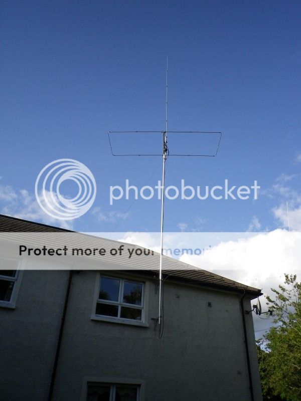
The EFHW and Moxon, this is were the BT101 will go up. If you look to the right you will just about see an imax in a tree!
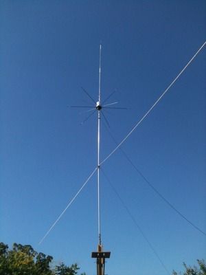
The BT101 astroplane/CTE top one clone in far from ideal location up a tree.

I got one of the last if not thee very last astroplane/CTE top one clones from a supplier here in UK a while back (a BT101 which is unbranded so I don't know who actually made them, but they are based on the original and NOT the new Sirio Top One). It's going back up soon to replace my halfwave end fed.
I remember seeing the original astroplane's up on houses in the mid 80s when I first came on to CB and thinking what the heck is that!. Anyway I've learnt a bit since then!
I did some A to B unscientific comparisons recently between the end fed half wave and the BT101 and though circumstances were far from equal between the two it gained me enough to make my conclusion.
The EFHW is mounted about 35ft up directly above a moxon beam with about 70ft of RG213 to the radio.
The astroplane clone was mounted about 30ft up a tree with about 95ft of a lesser quality coax (RG8 mini). So far from equal but anyway.
Results I got were based on local contacts obviously with DX propagation not being consistent enough to base how good an antenna is with too many variables.
Anyway to cut a long story shorter, the BT101 is the quietest (as far as static noise goes) vertical I have used based on memory from all the vertical antennas I have used including the Sirio GM, Imax 2000 with and without radials and the Sirio GP 1/2 wave.
On the recent test signals on the BT101 were perhaps an 'S' point lower than the EFHW above the moxon, BUT that lower signal was yielding much more audio and less background white noise. Typically on my EFHW the S meter sits at about S4 of crackly white noise were the BT101 would have an S2 or S1 of lower volume hash noise.
Signal wise on TX to a friend about 10 mile away who uses an original astroplane said my signal was more consistent, less wavery and very slightly higher using the BT101, on RX though his signal to me was slightly lower on the BT101 compared to the EFHW, bearing in mind this was on SSB.
These where blind test and I told him antennas where antenna A and antenna B just incase of any bias!
On AM and FM he said the signal on the BT101 was lower than the EFHW by an S point or even 2 S points (so the opposite results from SSB..?), my incoming signals on AM/FM were lower on the BT101 than the EFHW BUT there was less noise floor making the BT101 appear to be more 'cleaner' sounding.
Anyway I think with the better and shorter run of coax and mounted that little bit higher the BT101 clone will be as good as anything else with the bonus of no wind load hardly and a lower noise floor (and 27MHz around here has got considerably louder with noise over the last few years for some reason), of course my moxon beam will need to come down as it will be impractical to mount the BT101 above that, i'm struggling with lifting the poles, beam, rotator and coax's as it is so it will be a welcome relief to mount the lightweight BT101.
I'm still yet undecided if I will replace the capacitance loaded top section with a 1/4 wave yet, though I'm thinking if the original astroplane top was shortened for the reason to keep within the height restrictions of the time why have Sirio not put a 1/4 wave section on their new top one (now that there is no height restrictions) unless of course the benefits are so small as to be unnoticable? then again the astroplane clearly states in their patent that it's more efficient with a 1/4 top.. I dunno, guess i'll try it soon when I get the loan of an analyser and see for myself.
The EFHW and Moxon, this is were the BT101 will go up. If you look to the right you will just about see an imax in a tree!

The BT101 astroplane/CTE top one clone in far from ideal location up a tree.

i would never think about getting a fiberglass antenna as i have read & seen pictures of fiberglass antennas after they have been hit with lightning from thunderstorms as fiberglass antenna`s seem to attract lightning & well not much left afterwards as fiberglass ends up having splinters & the coil burnt out inside the antenna
but i guess to protect the radio from getting hit with the lightning i thought everybody knew to unplug the coax from the radio to the antenna while there is a thunderstorm near there location,
but even smaller antenna`s like the sirio boomerang can do a good 20 30 miles on FM & does pretty well in to Europe on 10 meters & i did read some where that a guy in California while using a boomerang made a contact in to Florida.
I read on one website that one guy unplugged his coax from his radio but he run his coax behind his appliances. After a lightning strike I think he had to redo that part of the house.
dxChat
- No one is chatting at the moment.