• You can now help support WorldwideDX when you shop on Amazon at no additional cost to you! Simply follow this Shop on Amazon link first and a portion of any purchase is sent to WorldwideDX to help with site costs.

Maverick 250 10m transmit fail

RobInSTL5150

Member
Jan 11, 2022
19
3
13
55
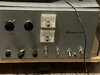
Playing with an old Maverick 250 amp and coming up at a loss with my semi-limited electronic knowledge with a problem on the 10 meter setting. For what I know of this unit the last time it was used the choke on the top had cooked and the unit was shelved after it was replaced. Tubes seemed shot but were not tested on removal. Put in a full set of tested and strong tubes. fired it up. Radio is a 10 meter radio (anytone Q6) and set at about 1/3rd power. I do get transmit and reduced output on the 15 meter setting and close to 400 watts. When I drop to 10 nothing. The key circuit is engaging and disengaging as normal and by all accounts everything looks like it should be running but there is no amp output at all. All other knobs, switches, meters and such operate normally.

A second matching amp I have here reacts identically on the 15 meter band so it appears the amplifier portion is working fine along with the tubes.

I can replace many parts in these things. I sadly have little knowledge in trying to diagnose something without a burnt part or obvious failure. Any suggestions welcome!
 

Not an expert, haven't stayed at a Holiday Inn Express either, but have you checked the band switch/selector to make sure it's engaging/has continuity on the 10M setting?
 
Ah, when you select the 15 meter band on the amplifier are you using a radio that's operating on 15 meters?

Or are you driving it with the 10-meter radio with the amplifier set for 15?

If so, this really makes it sounds as if the band switch itself is bad. Most of them don't perform all that well on 15 meters to begin with. We adopted the policy of removing the extra coil lengths connected to the band switch, leaving only an 11-meter coil underneath for the driver and on top for the final stage. Started doing that around the second time we saw that switch break down and arc inside.

Assembly details were changed in this model from year to year, so the exact hookup in yours may not match another one that's newer or older.

73
 
Ah, when you select the 15 meter band on the amplifier are you using a radio that's operating on 15 meters?

73

Right now that is my thought because I just can't find anything else near the switch that would affect it and for what I see the selector is just picking which wire goes to the coil on the top side. I wonder if since I have no need for the higher bands if I can just bypass the switch and jump the incoming and outgoing wire for the right band.

These units are confusing as there are more than one design and schematic and even two Maverick's I own are not designed the same (my good one has extra switches on the back and extra components there) but I believe the one being repaired is an original as it doesn't even have the three prong plug on it as my other models do.

I suspect it's time to mess with the switch itself and see where I get.

And yes was using a 10 meter radio and even tried from the 11 meter band. Both engage the key circuit/relay but no 10m output, up to 400 on 15.
 
Any suggestions on how I would go about that? For what I see most of it looks like leads to the coil and the sheer lack of a good schematic on these things has me a bit confused how to approach it. Just doesn't look like a simple connect this over to that and it's bypassed but not sure how to approach that mess down there.
 
Two relays. Guess it to be a pretty early version as it's a two prong ungrounded plug. And while it is not marked on there for 10 the knob does in fact go to four positions.

The second Maverick I have has a two prong grounded plug, 'D & A' in the meter backs, a two way toggle marked for 40-20/15-10, a grid tune knob and a switch simply marked BF (no clue). I do believe there is a tan fronted one that looked similar to the PDX 400.

I imagine the band knob should be pretty universal though but there are things with this one that doesn't match a lot of what I see out there.
 

Attachments

  • IMG_3181.jpg
    IMG_3181.jpg
    760.9 KB · Views: 141
this one that doesn't match a lot of what I see out there.

I get the impression that the folks who built them were making "improvements" with each production run. And if you compare the wiring diagram for a 1970 F100 pickup to a 1979 model, you'll see the same kind of differences. Really seems like the small changes never stopped.

Big difference is there's no shop manual for the linear, no list of changes for each model year.

73
 
That does seem to be what happened because every one I come across has something a little different with them. I am hoping that they at least stayed a little consistent with the switch and control stuff because as suggested bypassing the switch is perfect as it's intended purpose would be 10m.
 
Tricky part is to get the correct turns count for the driver coil underneath, and the final tank coil behind the front panel above deck. You know it's trimmed properly when the Tune control (smaller of the two Tune/Load) peaks at TWO positions. Those controls have no mechanical end stop, and freely spin 360 degrees.

As a result, a control that goes all the way to one end without reaching a proper resonant peak will appear to show a peak. But only one.

A look behind the panel at a Tune control with only one peak reveals that it is positioned either with the plates fully apart, the minimum-capacitance end. Or with the plates fully meshed together at the max extreme.

Basic rule to compensate is not so tricky. A control stuck at its minimum setting indicates you need LESS. Can't make the capacitor any smaller, so the coil's inductance needs to be reduced until the Tune control reveals a peak somewhere between the extremes.

Likewise, if a Tune control is maxed with the plates fully together, what the circuit needs is MORE. Adding more capacitance is not the best remedy. But adding inductance by squeezing the turns closer together, or moving a tap wire to add a fraction of a turn to its length is the next move. Sooner or later you can bracket your target and obtain a peak with the control somewhere between its max and min extremes.

Once this is done, you'll see two separate positions of the Tune knob that show a peak. The peak is often sharper and easier to see on carrier alone. The two peaks might be 180 degrees opposite if the control is peaked at its dead center spot. Or the two peaks might be close together. What counts is that you have TWO.

73
 
After playing with it a bit and matching it with my good working one I was able to determine the switch has been at least somewhat bypassed. Looks like they took the wire from the 15 meter switch and moved it over to the 10 meter part of the coil thus the empty solder point. Also looks like for some reason they took either 20 or 40 out as well. Location is correct for 10 meter but not sure about the top side yet. For my guess is if they went this far they moved the other as well but haven't made it that far yet.

I also notice the key circuit does not match the schematic as my key circuit has a 10/150 cap in place and this one has a 10/450 cap there - considerably larger. Tried placing the normal one in line but the relay would just engage upon powering the circuit so put the current one back in place. It is definitely not an original but as it seems common with these Mavericks no two really match each other but a much more modern looking component sticks out.
 

Attachments

  • IMG_3169.jpg
    IMG_3169.jpg
    1.1 MB · Views: 111
The keying circuit in this amplifier is a bit like holding a broom upside-down in the palm of your hand. Some tubes won't want to release when you unkey the radio. Another tube in the same amplifier might be less sensitive and want to chatter the relay.

The drastic change you saw from changing that capacitor illustrates the sort of demented equilibrium that makes a tube-type keying circuit do its job. Well, both of them. To key when there is a carrier, AND to release the relay when there isn't.

A transistor is a better choice for this, but you would have to change the antenna relay to use a lower voltage. The relay used with the keying tube requires voltage too high for transistors.

No cheap and easy answer for this one, unless you persuade the original setup to be reliable. In that case, it ain't broke. No need to fix.

73
 

dxChat
Help Users
  • No one is chatting at the moment.