• You can now help support WorldwideDX when you shop on Amazon at no additional cost to you! Simply follow this Shop on Amazon link first and a portion of any purchase is sent to WorldwideDX to help with site costs.
  • A Winner has been chosen for the 2026 July 4th Retevis RA89R Giveaway! Click Here to see who won!

Midland 13-898B Low SSB Power Out

Justin B.

Active Member
Oct 15, 2024
109
52
38
71
I continue going through this neglected radio and I think I have got most of the gremlins exorcised except SSB power. Receive seems fine so I left the synthesizer alignments alone and I went through the transmitter alignments and have about 2.5W dead-key and 5-5.5 W modulated. I have set the SSB bias and carrier null but can only get a little less than 2W out on both USB and LSB.

The only adjustments that did not go perfectly is the USB and LSB carrier freq adjust. They are both off and adjusting the associated trimmers doesn't seem to have any effect on the frequency.

Just for grins I replaced ALL of the electrolytics on the audio and main boards, cleaned all trim-pots before adjusting, etc. Any ideas of what else to look at would be appreciated.

73,
 

I replaced ALL of the electrolytics on the audio and main boards
Good start. Eliminates a whole list of possible faults. There are a handful of slug-tuned coils/transformers that get peaked to align that radio. Most of them that are in the transmit chain are 10 mm square with a thin threaded ferrite slug inside. Many of them have a built-in capacitor that sets the frequency it will tune. When that capacitor fails it becomes an open circuit, but not one you can test. The resonant frequency of that coil not jumps upwards a few MHz. Increasing the coil's inductance will only partially make up for the lost capacitance in the circuit. It will cause the apparent peak position of the slug to be dead even with the rim of the hole in the can. This appears to be a resonant peak, but it isn't. The maximum inductance of that part is reached with the slug at this "flush" position. The dead capacitor causes the slug to be adjusted for more inductance to reach resonance. But it won't. It will just get "close" to being resonant at the end of its functional travel. Turning the slug clockwise reduces inductance, and the transmit signal falls off. Turning it counter clockwise makes the slug rise above the rim and also reduces inductance. Acts like it's a peak but it isn't.

Sometimes there's a cheat to fix this without replacing the 'can'. But not always. Your problem may lie elsewhere, but this is a hazard for old solid-state radios and easy to check.

73
 
  • Like
Reactions: 19wrc333 and doffo
I have went through the transmitter alignments and none of the slugs peaked anywhere near the top of the cans. I think this may wind up on the "someday shelf" alongside the Bengal SSB!
 
  • Like
Reactions: doffo
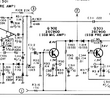
I started tracing from the mic amp to the balanced modulator and found that on the collector of Q302 (SSB Mic amp) instead of the 6.93 V I have right at 10V with a very small modulated signal riding on it. I popped out the 2SC900 and tacked in a 2n3904 and have the same results. I'm thinking this small amount of modulation after Q3 02 is maybe I don't have any output over about 2W on SSB.

Dig more tomorrow...

73,
 
I started tracing from the mic amp to the balanced modulator and found that on the collector of Q302 (SSB Mic amp) instead of the 6.93 V I have right at 10V with a very small modulated signal riding on it. I popped out the 2SC900 and tacked in a 2n3904 and have the same results. I'm thinking this small amount of modulation after Q3 02 is maybe I don't have any output over about 2W on SSB.

Dig more tomorrow...

73,
Sounds like you have it narrowed down! If the collector isn't being pulled down, check the base voltage. If that looks right, R314 may be open.
 

Attachments

Although it wouldn't explain 10v at the collector of Q302, I do believe the schematic value for R315 is wrong. I think it would be 2.1k, not 21k.
1785085242586.png
The schematic shows the base and emitter voltages at 2.1v and 1.5v respectively. For there to be 1.5v across R314 (820 ohm), there needs to be 1.5/820=1.83mA through it. To get 1.83mA through R315 (if it were 21k as shown), it would take 38.4v across R315. If, however, the schematic is in error and R315 is really a 2.1k resistor, the math would put 3.8v across it which would look a lot more reasonable given the noted collector voltage in the schematic.

This does not explain the 10v at the collector, but I wanted to point it out anyhow and ask what value is really in R315's spot. Maybe someone put a 21k there, and when that didn't work, they put something much lower than 2.1 in. Long shot, but worth looking at. Please share the base and emitter voltages when you get them.
 
Brandon - I get the following voltages on Q302:
E - +1.66V
B - +2.28V
C - +9.51V

The voltages when 2N3904 in circuit are similar. The base and emitter voltages are a bit higher then the print but the difference between them looks correct for a forward biased junction.

I found R313 a bit out of tolerance (12.55K instead of 10K) so I replaced that with no change. D303 and D304 test good. R315 has a 1K resistor installed. The Sams shows 1K with 21K in parenthesis so maybe this was a change during production. I'm going to put in a bigger resistor at R315 to see if the collector voltage will be more reasonable.

73,
 
  • Like
Reactions: brandon7861
2.1k would get it close to what the schematic shows, but I don't know if they had a reason to bias it higher. Maybe they were worried about the audio lows cutting off D303.

You should be able to squeeze a little more gain out of it by increasing C313.
 
I upped C313 to 10 uf and wound up with R315 at 2K and got about 6.4V at the collector but no more gain. Something is not right with that map stage or the input is a lot lower than it should be. Maybe I'll post up a couple scope grabs... After all of this messing around I can "yell up" about 2W out, now!

I think it's time to take my other 898B apart and make some comparisons...

73,
 
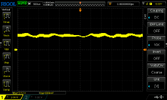
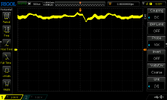
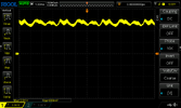
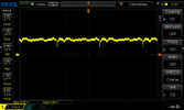
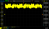
Brandon - I pulled the cover off my "good" radio and the collector has around 10V so I put the 1K resistor back in the fubar one. Here's scope grabs from base and collector of fubar and good.

First with r315 AT 2k.

Fubar Base:

fubar base.png

Fubar collector:

fubar coll.png

fubar with r315 at 1k

Base:

fubar base 1k.png

Collector:

fubar coll 1k.png

Good base:

good base.png

Good collector:

good coll.png

Quite a difference in the signals at the base so maybe the issue is before Q 302...

RV301 does affect power output and right now it is at max (fully CCW). I will take voltage measurements on U301...

73,
 
  • Like
Reactions: brandon7861
I agree, replace the 1k and focus on why the base signal is weak.

I had SSB on the mind, but going back to the top, I see your AM power is low too and that rules out the SSB-only stuff. Put the 1u cap back at Q302 since the issue is not there.

I would see what the MIC AGC voltage is (at C306, not at the base of Q301). I am just curious if there is enough voltage to turn on Q301 at the right side of R305. If the AGC is working to reduce the audio gain when you yell into the mic, we can assume the microphone and amp are working normally. If there is insufficient AGC voltage to turn on Q301 when yelling, you might have a loose mic wire, bad mic element or a weak IC preap.

Any chance of putting the wrong value cap in somewhere around this area?
 
I can modulate up to almost 6W on AM, is this actually too low? I'll check out the AGS stuff tomorrow. I'm done for today, my brain is about fried... I have tried the mic from the "working" radio with no change.

I think I got all of the caps right but I'll check.

73,
 

dxChat
Help Users
  • No one is chatting at the moment.