• You can now help support WorldwideDX when you shop on Amazon at no additional cost to you! Simply follow this Shop on Amazon link first and a portion of any purchase is sent to WorldwideDX to help with site costs.

Mobile Power Question

NEVER run negative straight to the battery. Run it to a point near where the main battery negative cable connects to the vehicle body/chassis.
Why "Never"?
I have seen factory body grounds that are 10 gauge and the heavy ground battery cable goes to the engine block. The common point where all the grounds meet up IS the battery connector.

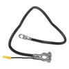
jeepbattery.jpeg
 
Last edited:
  • Like
Reactions: Eldorado828
Definitely need bigger wires. Wire is normally sized for amperage. But the voltage drop at that rating is too much for something critical like a high powered radio or amplifier. Car stereo guys go to great lengths to have as little voltage drop as possible. The voltage drop that is acceptable to you will determine the wire size. Definitely do the big 3 and for me, 2awg wire would not be out of the question.
2awg to replace what is currently in there as far as connections from the battery to ground and alternator to the battery? Radio is wired with 8 gauge. This is coming out of the radio to an Anderson connector. Then the same size from connector to the battery. Would you bump that up as well?
 
NEVER run negative straight to the battery. Run it to a point near where the main battery negative cable connects to the vehicle body/chassis.


Yes and No.

Closest vehicle hardpoint

Inches, not feet

(As per MOTOROLA).

Get the wiring circuit shortest

Seatbolt, etc.

In a car with short runs it won’t matter much except circuit amp draw.

TEST!


2awg to replace what is currently in there as far as connections from the battery to ground and alternator to the battery? Radio is wired with 8 gauge. This is coming out of the radio to an Anderson connector. Then the same size from connector to the battery. Would you bump that up as well?

Some “headroom” nice, but what’s radio fuse amperage?

Calls for 10 at 3% and you use 8? Could’ve used 12 based on majority of TX time. (8 is “nice”).

TEST

.
 
Hey Slowmover,

Looks like that is what I was mixed up about. I was reading it as the negative needs to terminate closest to the ground for the battery. This makes more sense. I have a seat bolt right next to the radio. I'll give that a shot. That would cut the circuit down by 10' or so. I should have figured that is what was meant as that is how my amp for the stereo is done. I could even cut out some length on the positive side. I do have a little bit extra tucked under the dash.
 
  • Like
Reactions: Tokin and Slowmover
4 awg minimal positive from battery to a car audio distribution block near the radio. The 4 awg blocks have 8 awg terminals to then go directly to the radio. Ground you could do the same with a distribution block but instead of battery, go to nearest body Ground.

I use this style of block but there are many made.20201109_210832.jpg
 
With a radio such as yours they consume lots of amperage/Voltage and need to be fed well to prevent the drop. Picture trying to breathe through a straw to sort of paint a picture for you. Now the lengths of smaller feed cable, picture trying to breathe through a 20' garden hose. The longer the run the more the drop.
Hopefully that makes sense.
 
  • Like
Reactions: Greyghost555
I'm only running a at-6666 in the commuter altima and I've done exactly as described above but with 8 awg to a block right underneath the center console to which the 12awg from the radio feeds from. Ground is directly to a point right next to the pos block on the car body.

One thing not mentioned is be sure to either fuse or circuit breaker close to the battery in case something rubs the cable and start a fire. The fuse is a must.
 
Hey Slowmover,

Looks like that is what I was mixed up about. I was reading it as the negative needs to terminate closest to the ground for the battery. This makes more sense. I have a seat bolt right next to the radio. I'll give that a shot. That would cut the circuit down by 10' or so. I should have figured that is what was meant as that is how my amp for the stereo is done. I could even cut out some length on the positive side. I do have a little bit extra tucked under the dash.


When I started driving big trucks it was a rule to severely limit Radio “on” time without the engine running.

It’s popular with some in the Amateur crowd to install an auxiliary battery to keep all wiring distinct from vehicle system wiring. It’s fairly involved to do it right (and expense is high) but it really won’t add a great deal of TX time.

On the 2020 Pete I’m in (built 8/19), I’ve four (4) Start batteries and a powerful diesel genset (plus inverter). With main engine off I can kick on that APU and run air-conditioning, etc.

I have two Volt Meters with which I monitor battery state. The Start batteries will disconnect at a voltage which enables re-start. I “might” kick in the unit for Radio but that happens maybe 2X yearly. (I’ve usually gone to bed within an hour of going Off-Duty).

So, short of a lot of idle time on your engine (not emissions-friendly) here’s a good excuse to get one of those little Honda generators you’ve been wanting. (No need for extra fuel. Keep trunk-lid cracked while underway.

A larger alternator, etc, can be more than it looks like. I’m in favor of it where it’s a straight bolt-in. Alternator controls are another matter. The whole can can double the price of the alternator, alone.

As an RVer I have a primary incentive for vehicle electrical upgrades. Radio is secondary.

So study Mr Applegate and then try to find someone else who’s modded your same vehicle in like manner.

Create parts list (credit card list). Tools and Supply also figure.

I’ve been happy to do these things, but, hell, I’m a truck driver. Can’t afford women, gambling, guns or fast cars. Indulge the nerd inside.

Expect that being new (again) to the hobby has both steep learning and wallet-depletion curves.

Mistakes = “man, I’ve got a really great box of spares!”

.
 
2awg to replace what is currently in there as far as connections from the battery to ground and alternator to the battery? Radio is wired with 8 gauge. This is coming out of the radio to an Anderson connector. Then the same size from connector to the battery. Would you bump that up as well?
Yes I would do 2 awg for everything. The 2 awg to the radio would need a distribution block at the radio. Then the radio can connect to that. The longer the run, the bigger the cable needs to be. Fuse at the battery is a must.
 
Last edited:
Yes I would do 2 awg for everything. The 2 awg to the radio would need a distribution block at the radio. Then the radio can connect to that. The longer the run, the bigger the cable needs to be. Fuse at the battery is a must.


The N3 is fused at 100A?

“Maximum Amp Draw” (based on radio gear fusing) as if that were a constant (to meet 3% voltage drop maximum).

6-AWG will 80A at 10’ and 50A at 15’
4AWG = 100A or 80A over the same lengths

The radio isn’t going to strain either.
These ARE NOT MINIMUM SIZES.

OP will do as he will, but whereas 6-AWG isn’t that hard to work with, 4-AWG sure starts to be so.

Cabling needs meet USCG standards, IMO.
All products used to deliver power: terminations, FR split loom, zip ties.
See ANCOR

.

.
 
Last edited:
The N3 is fused at 100A?

“Maximum Amp Draw” (based on radio gear fusing) as if that were a constant (to meet 3% voltage drop maximum).

6-AWG will 80A at 10’ and 50A at 15’
4AWG = 100A or 80A over the same lengths

The radio isn’t going to strain either.
These ARE NOT MINIMUM SIZES.

OP will do as he will, but whereas 6-AWG isn’t that hard to work with, 4-AWG sure starts to be so.

Cabling needs meet USCG standards, IMO.
All products used to deliver power: terminations, FR split loom, zip ties.
See ANCOR

.

.
I am not talking about what the wire will handle for amperage. I am taking about the voltage drop at that amperage. Some welding cable is rated using a 6v drop across the length of the wire. You want the radio to think that the battery and alternator are sitting right beside it. It all depends on how much voltage drop you can live with.
 
  • Like
Reactions: Slowmover and cralt
I am not talking about what the wire will handle for amperage. I am taking about the voltage drop at that amperage. Some welding cable is rated using a 6v drop across the length of the wire. You want the radio to think that the battery and alternator are sitting right beside it. It all depends on how much voltage drop you can live with.


3% voltage drop is too high?
That’s 13.5 to 13.0.

.
 
Half a volt here, half a volt there. Transient peak amperage will be higher than average. It could end up being more than half a volt. It depends on the length of the run too. Lots of things to consider.


It’s ALREADY oversized (Marinco 3% Voltage Drop AWG Chart).

The antenna WILL NOT be efficient as with a base station.

All that juice gotta go somewheres else.

I wouldn’t run that radio at more than 100W to start. It won’t benefit him on the road, and the antenna mount plus ground plane have limits.

Some of the Amateur crowd calls mobile antennas dummy loads (and rightfully so given the full range of what’s ideal for TX in ANY setup, type notwithstanding).

As before, the OP will do as he will.

The OP wants to remote-locate and use a field portable real antenna — where the car is 1,800-rpm genset & radio shack - I'd be more inclined to agree with the premise.

And, it’s not a half-volt here or there given supply quality and some rigor applied as best practice per the installation.

(See math formula at k0bg to account for losses)

I believe this contention would gain some traction if I could find it in (critical) marine radio or public service installations where Wattage is 100+. Didn’t find it on search several years back.

Pyrolysis
is then the concern.
High-heat operating conditions.

Again, see math formulas for ABYC standards where issues of legal liability apply.

E3075C5A-1F14-421F-9061-59F1AB116B93.jpeg
.
 

dxChat
Help Users
  • No one is chatting at the moment.