• You can now help support WorldwideDX when you shop on Amazon at no additional cost to you! Simply follow this Shop on Amazon link first and a portion of any purchase is sent to WorldwideDX to help with site costs.

Modelling a PDLII

warrior369

W9WDX Amateur Radio Club Member
This is the natural forum for any Avanti antenna.

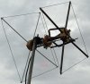
I've modeled and re-built my PDLII and wonder if I've made any obvious howlers.
I'll try and keep an eye on this thread because I have time to read but find it difficult to respond in early fashion.
btw. watching USA v Germany in the footie.
 

Attachments

  • My Avanti PDLII26Jul2014.pdf
    615.8 KB · Views: 767
  • Like
Reactions: 1 person

Quote from your document...

The other unknowns are the direction and magnitude of the currents. I've spent much head-scratching over this and I won't solve it till someone tells me wheather I've modeled it correctly.

I've modeled this antenna design before and your data looks similar to mine. I can't find those models at the moment so it will be difficult to post my version. To the best of my knowledge you appear to have modeled it correctly.

With currents and phase, the phase you have to use a different setting I believe. The phase uses the direction from the wire in question to mark current direction. Current strength is indicated in your document by how far the current line is from the wire modeled. I believe that these can be displayed together with EZNEC, however, I use another NEC2 based program so when it comes to EZNEC I am limited to what I remember about what I have seen.


The DB
 
Thanks for that.
I'll have another look in the settings to see if I can display phase direction.

Quote from your document...


I've modeled this antenna design before and your data looks similar to mine. I can't find those models at the moment so it will be difficult to post my version. To the best of my knowledge you appear to have modeled it correctly.

With currents and phase, the phase you have to use a different setting I believe. The phase uses the direction from the wire in question to mark current direction. Current strength is indicated in your document by how far the current line is from the wire modeled. I believe that these can be displayed together with EZNEC, however, I use another NEC2 based program so when it comes to EZNEC I am limited to what I remember about what I have seen.

Thanks for that.
I'll have another look in the settings to see if I can display phase direction.

The DB
 
Hi,

Yep, thats the software I used to get the initial dimensions for the folded dipole and the loop dimensions. I used copper pipe in my build, simply bent to shape. I'll post a picture of it asap.

73

I still have mine. :)

I remember a guy having a design on the internet, but his matching system used triangles instead of the globe style. Here's one I found that you could compare yours to:

PDLII for Windows. Ftparmy.com

73,
Brett
 
  • Like
Reactions: 1 person
I have always thought the PDLII was a cool design... small footprint, dual polarity, good f/b ratio for the boom length, etc. I know there are arguments against it because of the 1/2 wave driven element, but it sure seems to work good anyway.

73,
Brett
 
Hi Brett,

Hopefully, you can see the bent copper pipe matching section. Its a bit crudely done but should be OK. I had to increase the boom length because the matching section took a bit more real estate than the original 'globe' did. The original boom length was 58" and now its 73" long.

Yep, agree on your comments about performance and stuff. I've decided to concentrate on 20m and up from now on because I can't get any real height above ground for the low bands. I'm hoping I can use this type of design for 20m & 17m.

73


I have always thought the PDLII was a cool design... small footprint, dual polarity, good f/b ratio for the boom length, etc. I know there are arguments against it because of the 1/2 wave driven element, but it sure seems to work good anyway.

73,
Brett
 

Attachments

  • pdl2.jpg
    pdl2.jpg
    232.1 KB · Views: 217
I'm no Charles Ingell when working with wood and metal but thought I'd give this a go because it turned out so simple in the end.

It's almost impossible to find hubs for the PDLII so I used a block of wood for all 3 hubs. The image below is for a PDLII for 2m and if only I could believe EZNEC's performance data i.e. F/B at 48 dB, gain at 12.5 dB and a TOA of 15 degrees!! The average gain test was 1.08 and fairly confident it will work well but I am cautious on the modelled data.

I've been lcensed since 1985 and 2m SSB has always been my favourite band. I rarely use 2m now because its a real challenge getting out a signal due to all the mountains around where I live. Initial checks against a local beacon and numerous repeaters show its working as well as my previous long boom 10 ele crossed yagi from M2 - and that was a beast of an antenna.
If like me, you love how these antennas operate, a hard block of wood might be the answer to your next project.

I will attach the EZNEC model later plus info on how to tune it can either be found in the antenna Notes of the model or txt file for the non-modellers.​
 

Attachments

  • This_One_145MHz_H_0608_2014.txt
    3.5 KB · Views: 186
  • PDLII2M_SV0XBU.jpg
    PDLII2M_SV0XBU.jpg
    294.1 KB · Views: 222
  • Like
Reactions: 2RT307

dxChat
Help Users
  • No one is chatting at the moment.