• You can now help support WorldwideDX when you shop on Amazon at no additional cost to you! Simply follow this Shop on Amazon link first and a portion of any purchase is sent to WorldwideDX to help with site costs.

Navaho TRC490 No Transmit (PC385AG)

@brandon7861 Thanks for ideas.

Still trying to work out with the 0ma driver bias issue. Tried below with no change:

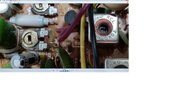
Lifted C215, no change.
Tried cleaning and adjusting VR8, no change still 0ma. Position was 1/3 up from anti clock wise (1/3 far from most left).

Replaced Driver 2SC1306 with a 2SC2166 ...I thought why not in case something was weird with 2sc1306. 2sc1306 tested fine first time out of circuit, now shows open between collector and emitter when removed. Glad I changed it out. I tested the 2sc2166 before putting it in.

On SSB TX, Drivers (2sc2166) base voltage is 0.23v, collector is 13.76v, Emitter = 0v (ie going to ground as per schematic)

TR38 collector shows 8v on TX.

Should I desolder VR8 and check it out of circuit? Its a 500 ohm pot.

What behavior would I see if D49 MV1Y is faulty? Its not shorted but was thinking of lifting a lead and checking.
 
When testing bipolar transistors, you should be looking for the expected forward voltage drop between the base-collector and base-emitter junctions.

Does your DMM have a diode test setting? Red on base, black to collector and emitter looking for 0.6 to 0.7v reading on each.

The diode in the bias circuit can be checked with the same meter setting, but to test it, it must also be out of circuit (as it is in parallel with the b-e junction of the transistor).

Check that diode next. Lift one leg and use the diode setting to see if it is good. I know there is no need to, but I feel I should add this... Don't turn the radio on with that diode out of circuit unless the driver's collector jumper is disconnected or the transistor will turn on and get very hot.

If it is not the transistor Vbe junction shorted, or the bias diode shorted, or the capacitor C215 shorted pulling the bias voltage down to 0.23v, then it is safe to assume that it isn't getting enough current for the voltage to go any higher. That suggests the pot. What voltages do you get on the pot legs?
 
  • Like
Reactions: Cable Guy
You can check the pot without pulling it out too. Verify the diode drops of the transistor and diode first, then if those are good, put them back in circuit and then do this:

If you measure the voltage across R152 (I am assuming it is good, no reason it shouldn't be), you can divide that voltage by its resistance to get the current through it. That current is the same as the current going through the pot. If you then divide the voltage you see across the pot by that current, you get the resistance of the pot. Should be under 500Ω. If that math don't work, replace the pot.
 
Last edited:
...and if the original driver tests good with the DMM in diode mode, put it back in. That R151 C152 feedback network is specific to the transistor it came with and using a transistor with a different (higher) gain can cause oscillations. I didn't look those values up to compare, just pointing it out.
 
im with Brandon on this one.

i was going to suggest the same thing he did.
try to set the bias.
driver bias of 0v regardless of the trimmer setting points right to that bias diode..

pull the leads out of the PC board and test it using the diode function of your DMM.
should read a small voltage somewhere around .3 to .7 volts in one direction and should read open in the other direction (switching the positive and negative leads around).

my guess is that you are going to find the bias diode for the driver open in both directions.

if you can remember, were the trimmers for the driver and final turned all the way one direction when you first opened the radio?
LC
 
  • Like
Reactions: Ghetto
my guess is that you are going to find the bias diode for the driver open in both directions.
Open components don't pull down voltages. Either the diode is shorted or the pot is bad. It could be that the shorted diode cooked the pot (both bad). edit: wrong on that last comment, even a short there shouldn't cook the pot. That only adds a little voltage to what it regularly sees anyhow. I am back to one or the other lol
 
Last edited:
  • Like
Reactions: Ghetto
Thanks for the replies, I'll start working through your tests.

@brandon7861

I am using Diode mode on the DVM, the C1306 is showing open between collector and Emitter when I have the black lead on collector (center pin) and red lead on emitter (right side pin). Swapping leads around also shows open. Open both ways instead of acting like a diode in one direction only...Writing of transistor facing me as I test it.

I think it was late night stuff up not testing it right the first time round.

I thought I'd read somewhere the C2166 was compatible/drop in to C1306. I read your message late one night and went looking online and found genuine C1306 are still available. So I have mail ordered a
C1306 given your saying the bias circuit is not setup for the C2166. Unfortunately it will take a few weeks to get from Canada to Australia (my QTH)


CHECKED OK:
D49 MV1Y (tested out of circuit)
R150
R151
R152
C152 (tested out of circuit)
C215 (tested out of circuit)

On transmit USB , R152 on end closest to VR8 shows 8.14v, so 8.14 divided by 220 = 0.037A (37ma)

Attaching a pic, realized my writing on pic is too small but the trimmer VR8 (Driver) has 8.14v on one side and on the other side has 0.29v (closest to L33 in pic). So am I using the 0.29v to measure resistance of pot?

Can I ask a beginner question, Can I take resistance measure of trimmer from its two feet ignoring the wiper? I feel like I can measure the finals trimmer (500k ohm) ok but drivers trimmer (500 ohm)not showing me anything unless I am on mega ohms...


@loosecannon

Trimmers for both driver and final were a little less then half way from anti clockwise furthermost position as per pic. ie no driver/final trimmers maxed out, but I found VR7 (I think ALC adjustment) maxxed out? (fully clockwise)
 

Attachments

  • trc490 vr8.jpg
    trc490 vr8.jpg
    523.7 KB · Views: 3
Thanks for the replies, I'll start working through your tests.

@brandon7861

I am using Diode mode on the DVM, the C1306 is showing open between collector and Emitter when I have the black lead on collector (center pin) and red lead on emitter (right side pin). Swapping leads around also shows open. Open both ways instead of acting like a diode in one direction only...Writing of transistor facing me as I test it.

I think it was late night stuff up not testing it right the first time round.

I thought I'd read somewhere the C2166 was compatible/drop in to C1306. I read your message late one night and went looking online and found genuine C1306 are still available. So I have mail ordered a
C1306 given your saying the bias circuit is not setup for the C2166. Unfortunately it will take a few weeks to get from Canada to Australia (my QTH)


CHECKED OK:
D49 MV1Y (tested out of circuit)
R150
R151
R152
C152 (tested out of circuit)
C215 (tested out of circuit)

On transmit USB , R152 on end closest to VR8 shows 8.14v, so 8.14 divided by 220 = 0.037A (37ma)

Attaching a pic, realized my writing on pic is too small but the trimmer VR8 (Driver) has 8.14v on one side and on the other side has 0.29v (closest to L33 in pic). So am I using the 0.29v to measure resistance of pot?

Can I ask a beginner question, Can I take resistance measure of trimmer from its two feet ignoring the wiper? I feel like I can measure the finals trimmer (500k ohm) ok but drivers trimmer (500 ohm)not showing me anything unless I am on mega ohms...


@loosecannon

Trimmers for both driver and final were a little less then half way from anti clockwise furthermost position as per pic. ie no driver/final trimmers maxed out, but I found VR7 (I think ALC adjustment) maxxed out? (fully clockwise)
You misunderstood a few things I said.

Diode mode don't work between collector and emitter, just test base to collector and base to emitter. Don't worry about collector to emitter right now.

I didn't say you couldn't use a 2166, I simply stated that if the original tests good, leave it in. And it had nothing to do with the bias, it has to do with the feedback components that limit gain to prevent oscillation. Not saying it will oscillate, just saying watch for that when swapping with different parts.

You also misunderstood the voltage/resistance part (but it don't matter, see my next post). When I say the voltage across the resistor, I didn't mean from ground to one side of it, I mean just across it. If you are going to use ground as a reference, then you must measure both sides of the resistor and find the difference. For example, you said there is 8.14v on the end of R152 closest to the trimmer. What is the voltage on the other side of R152? Should be the regulator voltage, 8.2v to 8.5v, somewhere in there. The difference of those two (or what your meter says measuring with the probes directly across R152) is the voltage you divide by 220Ω. It's not 8.14v/220Ω, there is not 8.14v across R152, its less than a volt there.
 
Last edited:
  • Like
Reactions: Ghetto
The fact its 8.14v says enough. Just replace that pot.

Even if your 8v regulator was at 9v and you had a whole volt across R152, thats 4.5mA. Since you have 7.85v across the pot, 7.85/4.5mA=1744Ω, higher than the pot should be. That pot is 100% for sure toast.
 
  • Like
Reactions: Ghetto
@brandon7861 Thankyou so much mate for your help. Sorry for the delay in reply. Just been very busy on other things the last few weeks but I had to come back to tell you:

Today I finally changed VR8 Driver 500ohm trim pot and the radio is up and running, I now have TX output!!. My first radio I've repaired!! Bouncing of the walls right now...

Took the c2166 driver out and put back in the original c1306 driver that passes your test above. I was testing using this method for a c1969 that I thought what work on driver transistors:
Is this testing method wrong? Just so I know in future.

Driver bias set to 30ma
Final bias set to 50ma (was originally at 30ma)

Radio on frequency TX and RX, noticed I think AM carrier is down compared to my other radios but swings well on SSB. Good modulation on AM and SSB. I'm using the forward mode of my inline SWR meter to ballpark watts output compared to my other radios but will have to buy a power meter so I can check/set this. Also have to do the service bulletin #1226 now the radio is working.

Thanks for the advice on measuring voltages and telling me where I am going wrong. I've learnt a lot from you and I appreciate your patience and help.

Anyone else that contributed : thank you so much for you input as well!
 
Rock on, Ghetto! Congratulations for sticking with it.

A transistor tester is a cheap fleabay item these days. The diode test between base and emitter, and between base/collector is valid for all bipolar transistors.

Just to make things more complicated, some transistors have a so-called "parasitic" diode between collector and emitter.

Most bipolar transistors don't. I got tired of keeping track which ones do and don't. Copped out and adopted the use of 30-buck chinesium transistor testers from fleabay. They're probably cheaper these days. As a rule, they won't get fooled by the parasitic diode.

73
 
The diode test between base and emitter, and between base/collector is valid for all bipolar transistors.
Thanks for clearing that up and extra detail on parasitic diodes. I've been looking at those cheap fleabay chinese component testers for a while now. Ill buy one shortly because I need that for capacitor testing as well. My cheap DMM can only read up to 20uf...


Rob
 
Finally, AM carrier was low due to someone turning down VR6 (AM POWER). I just turned it back up and carrier came back to where it should be.
 
  • Like
Reactions: Cable Guy

dxChat
Help Users
  • No one is chatting at the moment.