• You can now help support WorldwideDX when you shop on Amazon at no additional cost to you! Simply follow this Shop on Amazon link first and a portion of any purchase is sent to WorldwideDX to help with site costs.

Need alignment,frequencies points?

That came with the radio. I just bought this on ePay,$29.00 + $5.99 shipping. I was not told this was in the radio,I found out by taking the cover off and seeing if this radio was a virgin. Well,that's when the kids saw my pot turner and started turning the pots,as I had a phone call,and left the radio on the kitchen table. And you know what happened,my son saw me do this on a other radio,when we were at my buddies home,in his shop.I did not get anything done. I am curious, L19 and L23 work together to get the TX? L24 is for 10.240, and check 10.240 on TP2, RX Frequency is on TP3, how to get TX,and where to check frequency? This is what I am looking for,it is a little hard to understand some things,but I am trying.This is what I think I have for frequencies,
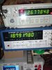
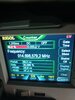
TP2,,,RX-10.240
TP3,,,,RX-20.063,,,,,,,TX-15.870
TP4,,,,,,RX-38.788,,,,,TX-39.766
These don't make sense to me but 10.240
Just need to know turn which pots for which frequency, and where to monitor TX and RX. Thanks,talk more later,thank you for the info...
 
Was the thing working before the "pots got turned?"

Right now, knowing by what I see in that card, focus your efforts on TP3 - that is a pipeline to monitor TX as well as RX IF frequencies - the card "swamps" that out - but you need TP3 to even see if the Radio can produce the frequencies to make the channels work.

The 15MHz looks like it's "wiping out" the regular CB channels, but the card is giving you frequencies your radio CAN'T use - so you need to make some choices.

Do you remove the extra channels or keep them in - I don't have the radio in front of me to help guide you - the Foil side on the radio might provide some clues as to what they did to install it.

Because you have "double" frequencies...

But to see the photos without the unit - then the unit (poof) appears - the extra channel "board" takes over the 10.240 Xtal and injects its own signal to take it's place.

How was I supposed to know? I didn't put the board in there.

So I imagine our issue with the missing, incorrect, or just plain goofy - frequencies, is from the board generating this and it's wiring issues.

The turning of the pots doesn't help any. There may have been some damage done.

I can't tell you what your exactly to do or need to know because I am only working with the information you're giving me. You should have said something earlier sooner in the thread about the extra board - I would have worked in a vastly different direction - you will have to remove the board to realign the radio - then re-install the board to obtain, get back, what you bought from eBay.

If you can't use what I've supplied, others can to help you figure out that extra channels board. You may be in over your head so take it to a tech - that card is screwing up your day.

Right now, until you somehow disable the card, you will see frequencies generated by that card and they will interfere with you ability to realign the radio so you can undo what was done.

You want the "extra" channels in there? We have a problem with that. We can't fix the radio or even know if there is even a problem with the radio - with the board in place, you have to remove it and restore the CB to it's original - then we figure out if there ever was a problem - fix that, realign it correctly - then we reinstall the board.

We don't even know if the crystals used on that board are working correctly - I've seen eBay "bargains" that are nothing more than resurrected radios with stuff thrown inside them to "value add" to the sale and someone was lucky enough to bid on it.

IN your case, those trimmers on the card take over the trimmer frequencies the radio would otherwise have used from it's own 10.240. But 15MHz is a bit low so that means lowers, but the 38+MHz tells me there is potentially some damage or a switch wiring issue - so whatever the eBay seller did to it - I am only guessing.

You're frequencies - at least for that radio - need to go up in MHz closer to 16MHz and you also have to find where they inject those frequencies so you can review the install - you just may have the wrong Xtal and with the turning of the pots - you may have cracked forms in there - we wouldn't know until we get the radio back to OEM - then we can figure out if anything got broken - fix it - reinstall and move on.
 
Last edited:
  • Like
Reactions: Shadetree Mechanic
Hey,if you want, let's pretend the channel board is not there? I can work with it,I will examine this board and see where my 10.240 MHz is. I am home all day today,no wife,no kids, all alone and very QUIET !!!!!!!.
It is so quiet here,I don't know what or why and with whom am I. Huh, did someone speak.not used to nobody being home,as I have about 2 hours of peace to work on the radio. Will update you when and if I find something. Later.
 
Was the thing working before the "pots got turned?"

Right now, knowing by what I see in that card, focus your efforts on TP3 - that is a pipeline to monitor TX as well as RX IF frequencies - the card "swamps" that out - but you need TP3 to even see if the Radio can produce the frequencies to make the channels work.

The 15MHz looks like it's "wiping out" the regular CB channels, but the card is giving you frequencies your radio CAN'T use - so you need to make some choices.

Do you remove the extra channels or keep them in - I don't have the radio in front of me to help guide you - the Foil side on the radio might provide some clues as to what they did to install it.

Because you have "double" frequencies...

But to see the photos without the unit - then the unit (poof) appears - the extra channel "board" takes over the 10.240 Xtal and injects its own signal to take it's place.

How was I supposed to know? I didn't put the board in there.

So I imagine our issue with the missing, incorrect, or just plain goofy - frequencies, is from the board generating this and it's wiring issues.

The turning of the pots doesn't help any. There may have been some damage done.

I can't tell you what your exactly to do or need to know because I am only working with the information you're giving me. You should have said something earlier sooner in the thread about the extra board - I would have worked in a vastly different direction - you will have to remove the board to realign the radio - then re-install the board to obtain, get back, what you bought from eBay.

If you can't use what I've supplied, others can to help you figure out that extra channels board. You may be in over your head so take it to a tech - that card is screwing up your day.

Right now, until you somehow disable the card, you will see frequencies generated by that card and they will interfere with you ability to realign the radio so you can undo what was done.

You want the "extra" channels in there? We have a problem with that. We can't fix the radio or even know if there is even a problem with the radio - with the board in place, you have to remove it and restore the CB to it's original - then we figure out if there ever was a problem - fix that, realign it correctly - then we reinstall the board.

We don't even know if the crystals used on that board are working correctly - I've seen eBay "bargains" that are nothing more than resurrected radios with stuff thrown inside them to "value add" to the sale and someone was lucky enough to bid on it.

IN your case, those trimmers on the card take over the trimmer frequencies the radio would otherwise have used from it's own 10.240. But 15MHz is a bit low so that means lowers, but the 38+MHz tells me there is potentially some damage or a switch wiring issue - so whatever the eBay seller did to it - I am only guessing.

You're frequencies - at least for that radio - need to go up in MHz closer to 16MHz and you also have to find where they inject those frequencies so you can review the install - you just may have the wrong Xtal and with the turning of the pots - you may have cracked forms in there - we wouldn't know until we get the radio back to OEM - then we can figure out if anything got broken - fix it - reinstall and move on.
Andy,I will get a pic of the back of the radio, foil side. I just noticed something while I got to work on the radio, there is a problem with the volume, it is real low. There is a possibility I may have smoked something when I was tuning the receive the other nite. I did not notice,but I did today checking frequencies. I will look at the Caps, I put a Amp in it when I first looked at it,nothing from P.A., and no receive. I hear it,but faint.
I was able to get the radio at 10.240MHz,I put a lead on the Capacitor near the Crystal, the one with the Brown or Yellow dot on them.Thats where the Sam's Photofact tells you where to get the 10.240 frequency.So it worked just fine,I turned L24, the one with the Crystal on it's side. Went real smooth, turned it in about 1/4 way in it just a hint more. Locked in with no problem. I hooked the counter to R8, it has a hump and clean leads, I would think that is a frequency lead, it is sitting at 26.9285, this is what it reads. So some where I am almost at 27.185,, this is the channel I am on. I will see what I need to do,I am going to go over some of the posts you sent back to me,there is a lot of information, but it seems to go over my head. The things you are giving me are very technical,something a teacher should say to his class,when he is teaching how to fix a Transceiver. But it is very interesting on how the radio works, it is more like a science, very technical how Transistors shut off to allow this Diode the turn on,sending current to this cap, energizing this whatever. That is pretty heavy having to memorize all if that, I think my head would explode, to much input. Talk soon,my quiet time may be over,I hear a car,crap.Later....
At my buddies house,brought the radio over here. OK,top freq counter is TP4
second freq counter under first counter is TP R22,,,, Resistor.
Next last freq counter on the Generator,
TP3.
TP4,,,,,26.744MHz
TP, Resist 22,,,,,,18.976MHz
TP3,,,,,,14.745MHz
Numbers look better, I align the whole radio, I think. I peaked the TX, peaked the receive,,have 10.240 MHz,I have 3.2 Volts on VCO. But I don't have TX or RX, I am going to check voltage on Amp. I read your posts,understood a fraction,but very good learning information. OK, now I am stick,going to hopefully have RX,gonna see what I can do,look at the audio section,I guess I am gonna learn schematics. Talk soon.wish me luck.
 

Attachments

  • 16266618981652486341879416580840.jpg
    16266618981652486341879416580840.jpg
    4.4 MB · Views: 4
  • 16266619507512296303835915854453.jpg
    16266619507512296303835915854453.jpg
    3.9 MB · Views: 5
  • 16266660249822363775006949210842.jpg
    16266660249822363775006949210842.jpg
    2.4 MB · Views: 5
  • 16266660695487025250260491638625.jpg
    16266660695487025250260491638625.jpg
    2.5 MB · Views: 5
Last edited by a moderator:
Thank you, I don't know if you can see this thru the glare from the photo...
upload_2021-7-19_7-25-51.png
You seem to be missing a Diode D16 the "Delta tune" side - the one that uses L24 and L23 (10.240)

upload_2021-7-19_7-36-1.png

Seems to be missing...I see D13 for the PLL's L19 - but not for D16 L23 combo

The D13 is not stock, but L23 DOES NOT NEED a Varactor for those radios without the Delta Tune (uses Dimmer in it's place), but you need to verify that the 10.240 will "shift" for you using L23 and C131 - so you say you're getting 10.240 - so if you're ok with this... - IMHO - D13 may actually be your bigger problem since the Diode is not stock can't see numbers - this may be from the eBay installer using a different diode for the PLL's "slide".-doesn't always work.
 
Last edited:
Andy,I will get a pic of the back of the radio, foil side. I just noticed something while I got to work on the radio, there is a problem with the volume, it is real low. There is a possibility I may have smoked something when I was tuning the receive the other nite. I did not notice,but I did today checking frequencies. I will look at the Caps, I put a Amp in it when I first looked at it,nothing from P.A., and no receive. I hear it,but faint.
I was able to get the radio at 10.240MHz,I put a lead on the Capacitor near the Crystal, the one with the Brown or Yellow dot on them.Thats where the Sam's Photofact tells you where to get the 10.240 frequency.So it worked just fine,I turned L24, the one with the Crystal on it's side. Went real smooth, turned it in about 1/4 way in it just a hint more. Locked in with no problem. I hooked the counter to R8, it has a hump and clean leads, I would think that is a frequency lead, it is sitting at 26.9285, this is what it reads. So some where I am almost at 27.185,, this is the channel I am on. I will see what I need to do,I am going to go over some of the posts you sent back to me,there is a lot of information, but it seems to go over my head. The things you are giving me are very technical,something a teacher should say to his class,when he is teaching how to fix a Transceiver. But it is very interesting on how the radio works, it is more like a science, very technical how Transistors shut off to allow this Diode the turn on,sending current to this cap, energizing this whatever. That is pretty heavy having to memorize all if that, I think my head would explode, to much input. Talk soon,my quiet time may be over,I hear a car,crap.Later....
At my buddies house,brought the radio over here. OK,top freq counter is TP4
second freq counter under first counter is TP R22,,,, Resistor.
Next last freq counter on the Generator,
TP3.
TP4,,,,,26.744MHz
TP, Resist 22,,,,,,18.976MHz
TP3,,,,,,14.745MHz
Numbers look better, I align the whole radio, I think. I peaked the TX, peaked the receive,,have 10.240 MHz,I have 3.2 Volts on VCO. But I don't have TX or RX, I am going to check voltage on Amp. I read your posts,understood a fraction,but very good learning information. OK, now I am stick,going to hopefully have RX,gonna see what I can do,look at the audio section,I guess I am gonna learn schematics. Talk soon.wish me luck.
Chill Bro,all is cool now, I have all the necessary frequencies, and the extras are staying a extra and not seen until you change the Dimmer switch up one or down one. They are a little off, and that's where they are staying, the main freqs are AOK.
 
  • Like
Reactions: NightThumper
Chill Bro,all is cool now, I have all the necessary frequencies, and the extras are staying a extra and not seen until you change the Dimmer switch up one or down one. They are a little off, and that's where they are staying, the main freqs are AOK.
I did not notice the Diode missing,I look in the parts section, and D13 is not even on the book. I think I have seen this before,the missing Diode,I looked at 2 more radios at my Buddies house, they are also missing. Apparently Cobra did not want a D13, is 13 a lucky number or a bad number? Friday the 13th, oh boy, unlucky number, they removed the Diode due to a unlucky number. Now that is creepy.LOL
 
Man...

How do I even tell...

Refer to this post...
https://www.worldwidedx.com/threads/need-alignment-frequencies-points.262137/page-2#post-767878

D13 is your PLL's Varactor, that is there...is not a STOCK one normally found - refer to the link above...

upload_2021-7-19_7-25-51-png.45856


D13 is your PLL diode, D16 is the other one I was referring to...

You have a Cobra 29 NIGHT WATCH ...D16 is not supplied - they took away in the Delta Tune but put in a Dimmer.
I'd love to say that is normal but your board being a 1106 allows for it (the board) to be used in most of their 29's which can have a Delta Tune as an option - except the ST and WX types they use a different board.
You wanted to find Frequencies - you posted some of your results and now you have it working

Congratulations!
 
  • Like
Reactions: AudioShockwav
Man...

How do I even tell...

Refer to this post...
https://www.worldwidedx.com/threads/need-alignment-frequencies-points.262137/page-2#post-767878

D13 is your PLL's Varactor, that is there...is not a STOCK one normally found - refer to the link above...

upload_2021-7-19_7-25-51-png.45856


D13 is your PLL diode, D16 is the other one I was referring to...

You have a Cobra 29 NIGHT WATCH ...D16 is not supplied - they took away in the Delta Tune but put in a Dimmer.
I'd love to say that is normal but your board being a 1106 allows for it (the board) to be used in most of their 29's which can have a Delta Tune as an option - except the ST and WX types they use a different board.
You wanted to find Frequencies - you posted some of your results and now you have it working

Congratulations!
I have no receive,yet. But I have transmit,BUT,I have a carrier,but no modulation. I am having fights with the transmit frequency,I just cannot get it to 27.185, the channel I am on. This is completely tuned,3 times. I cannot also get the 3.20 V on the VCO, it is stuck at .873 V, and it will not adjust,it just stays there. For now,this is all the issues,so far that extra channel board is ,or seems, not to interfere with anything,maybe the transmit frequency? I will try again,maybe I will throw the generator on,and try to get it down,that's the issue,I cannot get it down,now I will have to get it up,LOL,the frequency,,,,,that's all I have for now. Thanks a bunch,talk soon,going to take a look at Transistor 21, see is it kicking 8Volts from center pin? That will mess up RX & TX, as I am told.Talk soon.
 
Man...

How do I even tell...

Refer to this post...
https://www.worldwidedx.com/threads/need-alignment-frequencies-points.262137/page-2#post-767878

D13 is your PLL's Varactor, that is there...is not a STOCK one normally found - refer to the link above...

upload_2021-7-19_7-25-51-png.45856


D13 is your PLL diode, D16 is the other one I was referring to...

You have a Cobra 29 NIGHT WATCH ...D16 is not supplied - they took away in the Delta Tune but put in a Dimmer.
I'd love to say that is normal but your board being a 1106 allows for it (the board) to be used in most of their 29's which can have a Delta Tune as an option - except the ST and WX types they use a different board.
You wanted to find Frequencies - you posted some of your results and now you have it working

Congratulations!
 
Thank you, I don't know if you can see this thru the glare from the photo...
You seem to be missing a Diode D16 the "Delta tune" side - the one that uses L24 and L23 (10.240)


Seems to be missing...I see D13 for the PLL's L19 - but not for D16 L23 combo

The D13 is not stock, but L23 DOES NOT NEED a Varactor for those radios without the Delta Tune (uses Dimmer in it's place), but you need to verify that the 10.240 will "shift" for you using L23 and C131 - so you say you're getting 10.240 - so if you're ok with this... - IMHO - D13 may actually be your bigger problem since the Diode is not stock can't see numbers - this may be from the eBay installer using a different diode for the PLL's "slide".-doesn't always work.
You know Andy,when it rains it pours. I put based another radio off of
One more thing,the TX frequency is stuck at 77.877MHz,and really will not come down,I am thinking possibly that IC3 may be bad? What is your impression on this issue? And I am also having a hard time setting 10.240, the frequency keeps dropping to 00.000MHz,then reappears,dissapears then reappears,keep losing that one. What is your suggestion for I. Check back in a short.....One more thing,As for I think the 13 V line,I have a bunch of parts with no Voltage,I started by replacing TR5,if you keep going back,I have no voltage at all,I am possibly looking at a PLL. I have 5 volts I believe on pin 1, the first pin to my right looking at me,5V,but across from that,there is 0 voltage. I will try to back track those parts when I get a open mi ute,doing a few things for the wife.talk soon,thanks man.
 
Last edited by a moderator:

dxChat
Help Users
  • No one is chatting at the moment.