uhh the "kid" adjusted all the pots ??? sure it wasnt dad tryin to peak n tune without a roadmap? just kiddin but good luck

You are using an out of date browser. It may not display this or other websites correctly.
You should upgrade or use an alternative browser.
You should upgrade or use an alternative browser.
-
You can now help support WorldwideDX when you shop on Amazon at no additional cost to you! Simply follow this Shop on Amazon link first and a portion of any purchase is sent to WorldwideDX to help with site costs.
-
A Winner has been chosen for the 2026 July 4th Retevis RA89R Giveaway! Click Here to see who won!

When I was a kid, I had the space patrol walkie talkies. All those adjustments looked interesting and of course they were meant to be adjusted because a screwdriver fit them. So I adjusted a few but I couldn't tell if it made any difference when I hit the key and started talking. So I adjusted a few more. No difference on my end that I could tell.
Then one day, my sister and I got the bright idea to practice our cuss words on the walkie talkies. Being on a cb channel, someone told us to quit playing with our dad's radio. I told them that we were on walkie talkies and asked what channel we were on because I always wanted to know.
He said ALL OF THEM!!
Well for starters, you need to get a scope and look for signal at R85 (as needed) - and you maximize that signal by adjusting L22. You also need a DVM to check Varactor voltage at R88
OR if you have speaker and know how to listen for receiver noise, you can simply, listen for the noise - from the speaker - to tell you it is working.
- STOCK Microphone connected
- Power supply is no more than 13.8V DC and Regulated.

OR if you have speaker and know how to listen for receiver noise, you can simply, listen for the noise - from the speaker - to tell you it is working.
- You tweak L22 between Channel 1 and Channel 40 for rest RX noise" recovery times - equal amounts of time needed for RX noise to appear
- STOCK Microphone connected
- Power supply is no more than 13.8V DC and Regulated.
Turn it on,
Set VOLUME Control to 1/2 way point,
Install EXT Speaker or PA speaker -
Turn SQUELCH control fully CCW - turn it all the way down (off),
NB and ANL - OFF
SWR : CAL : S/RF to S/RF
CB/PA in CB Mode
Got a Green RX light?
Channel Display works? (Rotate channel knob make sure all segments do light no gaps)
Dimmer function - does it control the brightness of displays?
S/RF Meter light working?
All the conditions above must pass first to continue
Locate L22 and R88 / R85 - you may need to connect the Scope if you DO NOT hear or have not heard any receiver noise during the warm-up.Set VOLUME Control to 1/2 way point,
Install EXT Speaker or PA speaker -
- if you wish to check and verify PA function works - Check PA function now,
- Use and Adjust Dynamike and VOLUME - listen thru Speaker connected to the PA Speaker Jack
- Make sure Volume and Mic Audio work and can be controlled...
- Install EXT Speaker into EXT Speaker Jack (optional or use INTERNAL SPEAKER to continue test)
While that process is going on, continue to set up Radio...
Install a 50 ohm Dummy load on the Antenna jack,
Turn SQUELCH control fully CCW - turn it all the way down (off),
NB and ANL - OFF
SWR : CAL : S/RF to S/RF
CB/PA in CB Mode
Got a Green RX light?
Channel Display works? (Rotate channel knob make sure all segments do light no gaps)
Dimmer function - does it control the brightness of displays?
S/RF Meter light working?
All the conditions above must pass first to continue
Tune to Channel 1 - Adjust L22 - make sure you can hear hiss of receive noise...

L19 and R88 - Tweaking L19 affects R88's Voltage value
Tune (turn Channel Knob) to
Key up Radio and peaking RF OUT oat Antenna Jack into 50 ohm Dummy Load (or use S/RF meter)
 Locate L19 - TX Out
Locate L21 (Long case - twin slug) and L20 - for Start of TX-Strip Peaking
Locate :L20 IC3 Mixer Out Peaking Coil for TX
Locate L23 2nd IF and TX Mixer IF Out
L18 is 1ST IF - Checked at TP5 Bare Lead Jumper - RX-Strip Peaking
L7 - obtains 455kHz output into L8 and L9 (2nd IF 455kHz )
L23 mixes with L19 Out into IC3 - and L20 Peaking for 27MHz - L21 is BAND PASS filter and peaking for IC3 INTO L20.
If no noise, Re-check SQUELCH Function, MIC cord and handset and Volume controls.
Does PA work - verified earlier? OK? Then continue
Tune to Channel 40 - can you hear Receiver noise thru speaker?Does PA work - verified earlier? OK? Then continue
- if not stop here and make sure PA works - PA Works? - then continue
- if it does not, then stop here and repair audio/Mic amp paths - you have audio and speaker issues.
- if it does not, then stop here and repair audio/Mic amp paths - you have audio and speaker issues.
If no noise can be heard, and Previous Step you hear Receiver noise, adjust L22 and/or Squelch until you can hear Receiver noise on Channel 1 and Channel 40.
L22 if that coil works and you have RX noise, then locate L18 RX and L19 TX IF Peaking coils.- The above steps are important!
IF the radio is left stock - much of the emissions and related issues with dirty sounding radios can be avoided
- most of the tuning of this radio is to peak within the 27MHz band and will work just fine one these steps have been followed.
It is DESIGNED that way.
- most of the tuning of this radio is to peak within the 27MHz band and will work just fine one these steps have been followed.
It is DESIGNED that way.
Tune (turn Channel Knob) to
- - Channel 40 - R88 = ~3.2Volts (Approximate)
- - Channel 1 - R88 = ~ just above 1 Volt (Approximate)
- - Adjust L19 using Voltage Reading at R88 for Channel 1 and Channel 40
Key up Radio and peaking RF OUT oat Antenna Jack into 50 ohm Dummy Load (or use S/RF meter)
Locate L21 (Long case - twin slug) and L20 - for Start of TX-Strip Peaking
Locate :L20 IC3 Mixer Out Peaking Coil for TX
Locate L23 2nd IF and TX Mixer IF Out
L18 is 1ST IF - Checked at TP5 Bare Lead Jumper - RX-Strip Peaking
- In RX, first peaked using Channel 20.
L7 - obtains 455kHz output into L8 and L9 (2nd IF 455kHz )
L23 mixes with L19 Out into IC3 - and L20 Peaking for 27MHz - L21 is BAND PASS filter and peaking for IC3 INTO L20.
The above should help you get started...
If you've intentionally damaged a radio in an effort to prove something - then I will not continue to participate in this thread...
Although "wrestling" with radio is a classic metaphor, I am left wondering if you've intentionally done this in some twisted effort to prove a point
If you've intentionally damaged a radio in an effort to prove something - then I will not continue to participate in this thread...
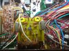
...Done done and done, dug it all out. Used a hot mini screwdriver. Take a butane mini torch and heat the end of the mini screwdriver, ( with the radio unplugged ) then when you think it is hot enough,run it through the wax. The hot screwdriver melts the wax,but sometimes it comes back when it cools. But there won't be much left as it all melted.. This is the way I clean the wax,ready to "Rumble". Pro wrestler.
Although "wrestling" with radio is a classic metaphor, I am left wondering if you've intentionally done this in some twisted effort to prove a point
W
work in progress
Guest
While I work on the home project...
Wanted you to go over YOUR work and fix that wax mess, we have to find Test Points in all of that...
Best to REMOVE some of the wax - just dig out components carefully and gently pry / lift / pull away wax so you can get access, for you will need to possibly Scope L22 if you can't get any RX noise to start this.
I didn't see one on your NW but if you have one, or muddeled (a Modification) in this one Be sure to Center your DELTA TUNE Knob Before you start this whole process.
Delta Tune is on SOME Cobra 29's but in the NW the DIMMER knob replaces it and there is no provision for it NORMALLY on the Night Watch - I've seen worse...
Why ask? Because when a radio doesn't have any RX or TX or both, there may be a botched mod in the Delta Tune area - killing power to the PLL - you have lights siren and all the stuff of radio - but no heartbeat because they killed the L23 (10.240 Crystal) section by trying to mod in a slider or some other similar concept.
I was playing a new Tic Tac Toe game,I use the pots for X's and O's. And who ever turns the pot to the bottom first,wins.uhh the "kid" adjusted all the pots ??? sure it wasnt dad tryin to peak n tune without a roadmap? just kiddin but good luck
W
work in progress
Guest
While I work on the home project...
Wanted you to go over YOUR work and fix that wax mess, we have to find Test Points in all of that...
Best to REMOVE some of the wax - just dig out components carefully and gently pry / lift / pull away wax so you can get access, for you will need to possibly Scope L22 if you can't get any RX noise to start this.
I didn't see one on your NW but if you have one, or muddeled (a Modification) in this one Be sure to Center your DELTA TUNE Knob Before you start this whole process.
Delta Tune is on SOME Cobra 29's but in the NW the DIMMER knob replaces it and there is no provision for it NORMALLY on the Night Watch - I've seen worse...
Why ask? Because when a radio doesn't have any RX or TX or both, there may be a botched mod in the Delta Tune area - killing power to the PLL - you have lights siren and all the stuff of radio - but no heartbeat because they killed the L23 (10.240 Crystal) section by trying to mod in a slider or some other similar concept.
No was watching wrestling on TV,stuck in my head,those stupid sayings that made them millionaire's. I have a million dollars question,is this picture going to hurt anything? What do do with this,I just found it¿A cut D11,,leave or fix.The above should help you get started...
If you've intentionally damaged a radio in an effort to prove something - then I will not continue to participate in this thread...
...
Although "wrestling" with radio is a classic metaphor, I am left wondering if you've intentionally done this in some twisted effort to prove a point
Attachments
W
work in progress
Guest
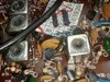
No was watching wrestling on TV,stuck in my head,those stupid sayings that made them millionaire's. I have a million dollars question,is this picture going to hurt anything? What do do with this,I just found it¿A cut D11,,leave or fix.
W
work in progress
Guest
If I were to intentionally do anything to the radio,it would be much more than a stinking pot turn. I would have made such a mess,and see if you could figure it out. I could have put 2 bad crystals in it,a bad resistor,I have a few. So,when all said and done,NO,I did not mess with the darn radio, I want to fix the ////// radio. Can you read between the lines.LOL,,no,I would not do such a thing to you or nobody,I am not like that,I don't screw over people I like,and consider the person being a cool person.Got it?????? No get that out of you head,( ass ) and let's work together. I apologize for the few bad words,but it all adds up,in the end.
No was watching wrestling on TV,stuck in my head,those stupid sayings that made them millionaire's. I have a million dollars question,is this picture going to hurt anything? What do do with this,I just found it¿A cut D11,,leave or fix.
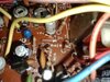
D11 is the AMC (Limiter) Diode - having it cut will only affect your TX Audio - Carrier is a DC voltage into the TX Strip from Audio Modulation Transformer the D11 uses - it "samples" from...
I've given you a LOT of information about this tune up - starting at L22 and L19 - and working to get the RX IF signals starting to communicate with the rest of the board.
The only problems I can see from this moment on is dealing with Voltage Regulation - your PLL needs 5V and the Tank circuits L22, L23, L24 and L19 - Need Regulated 8 Volts supplied on the main board.

D19 is a ZENER - Supplies 5V to Pin 11 and also Pin 7 - it also shows up on Pin 16
Pink circled area is PLL's Pin 11 - Pin 7 is under Ribbon Cable hidden from view.
D15 is the Transmit/Receive Shift pin, L19 and L18 are affected by the status of this pin - L19 / L23 to TX side, while L18 and L23 to RX side.
As far as RX goes, the flexibility to tune it up is left to you, L23 is predominate 10.240 2nd IF mix sent to L8/L9 and develops 455kHz while L18 is sent to the 1st IF FET by L3 and L4 - TP3 can use some help by tweaking L18 into L3 and L4 as a trio of tuning coils done together to balance the RF signal mixing into the 1St IF for the 1st IF strip L5 thru L8.
W
work in progress
Guest
I was only saying, I had that saying stuck in my head. A&E had a special on that wrestler who came up with that saying forgot his name, but boy, the steroids took a toll on that dude.
He looked to be 80, instead of late 50's early 60's, darn I cannot remember his name. But sorry if it offended you, I thought it was funny,got it off of my mind.OK,we are aligned,3.20 V at the VCO. I forgot to tell you.this radio has extra channels,they put the dial on the Dimmer switch,go either way.you go up,or you go down.27.415 to 27.855and lower are 26.515 to 26.915, that's all she wrote.
Going to go over your latest fix,it is 10.00 central time, I have 6 hours to get what you have for I to do. That brings it to 4.00AM,no problem. Have a great night,have to put the kids to bed. Later Alligator... LOL .
Attachments
W
work in progress
Guest
PllD11 is the AMC (Limiter) Diode - having it cut will only affect your TX Audio - Carrier is a DC voltage into the TX Strip from Audio Modulation Transformer the D11 uses - it "samples" from...
I've given you a LOT of information about this tune up - starting at L22 and L19 - and working to get the RX IF signals starting to communicate with the rest of the board.
The only problems I can see from this moment on is dealing with Voltage Regulation - your PLL needs 5V and the Tank circuits L22, L23, L24 and L19 - Need Regulated 8 Volts supplied on the main board.
D19 is a ZENER - Supplies 5V to Pin 11 and also Pin 7 - it also shows up on Pin 16
Pink circled area is PLL's Pin 11 - Pin 7 is under Ribbon Cable hidden from view.
D15 is the Transmit/Receive Shift pin, L19 and L18 are affected by the status of this pin - L19 / L23 to TX side, while L18 and L23 to RX side.
As far as RX goes, the flexibility to tune it up is left to you, L23 is predominate 10.240 2nd IF mix sent to L8/L9 and develops 455kHz while L18 is sent to the 1st IF FET by L3 and L4 - TP3 can use some help by tweaking L18 into L3 and L4 as a trio of tuning coils done together to balance the RF signal mixing into the 1St IF for the 1st IF strip L5 thru L8.
W
work in progress
Guest
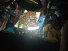
Real quick, the PLl is at 4.98V , D15= 8.79V , D19 5.13V, and both Resistors have 5.2V. Feel better,just tell me where to go,and I shall give it my best. Take a close look at the he picture, that thing had been bugging me for at least 1 hour, I warned it,he or she was going to get it. I smack it when it landed on my hand, and this is where it fell. Going to turn on the power, and see if he fries.️️️ Sorry, but this Fly deserves it,talk soon.
Attachments
W
work in progress
Guest
I was only saying, I had that saying stuck in my head. A&E had a special on that wrestler who came up with that saying forgot his name, but boy, the steroids took a toll on that dude.
He looked to be 80, instead of late 50's early 60's, darn I cannot remember his name. But sorry if it offended you, I thought it was funny,got it off of my mind.OK,we are aligned,3.20 V at the VCO. I forgot to tell you.this radio has extra channels,they put the dial on the Dimmer switch,go either way.you go up,or you go down.27.415 to 27.85, and lower are
He looked to be 80, instead of late 50's early 60's, darn I cannot remember his name. But sorry if it offended you, I thought it was funny,got it off of my mind.OK,we are aligned,3.20 V at the VCO. I forgot to tell you.this radio has extra channels,they put the dial on the Dimmer switch,go either way.you go up,or you go down.27.415 to 27.85, and lower are
I've seen worse...(UGH)
My only wish is that this is the ONLY bug we will actually have to deal with...
Are you still having problems with Frequencies with and without that board?
Why Do I mention that?
IF not, just skip this message else we'll have to research further and figure out our next steps.
(If so) We - Will need a good steady, well resolved picture of the Foil side. You'll need a good strong light and steady hands for this.

If you're not getting any Frequencies, the Varactor's - tiny little didoes - will need to chased down, found and checked - to keep it easier - just see if we can find them, then if they're missing or bad - we'll have to discuss which step to take next.
My only wish is that this is the ONLY bug we will actually have to deal with...
Are you still having problems with Frequencies with and without that board?
Why Do I mention that?
Because of this--:

This area, with all those empty holes,
- is where the TX and RX "merge"
- The Delta Tune area
- L19 and L18 branch off from here
- L19 to TX Strip and IC3 TX Mixer
- L18 goes to Handle 1ST IF Amp
YOU HAVE A GREAT BIG EMPTY
Although NW and some WX units do not have DELTA TUNE
They Do have SMD parts for FIXED RX and TX Frequency tracking,
Mounted On the FOIL side - The 2 IF Frequencies remain separate
-Delta Tune D16 side is Buffered and Sent thru L23 for both TX and RX modes...
- PLL D13 Still has 455kHz offset from VCO due to T/R Pin on PLL
IF not, just skip this message else we'll have to research further and figure out our next steps.
(If so) We - Will need a good steady, well resolved picture of the Foil side. You'll need a good strong light and steady hands for this.
If you're not getting any Frequencies, the Varactor's - tiny little didoes - will need to chased down, found and checked - to keep it easier - just see if we can find them, then if they're missing or bad - we'll have to discuss which step to take next.
Last edited:
You also posted this...

I didn't know your plans was to install frequency expansion at the same time...
")
(...you may be kinda on your own here...)
I didn't know your plans was to install frequency expansion at the same time...
(...you may be kinda on your own here...)
dxChat
- No one is chatting at the moment.