
You are using an out of date browser. It may not display this or other websites correctly.
You should upgrade or use an alternative browser.
You should upgrade or use an alternative browser.
-
You can now help support WorldwideDX when you shop on Amazon at no additional cost to you! Simply follow this Shop on Amazon link first and a portion of any purchase is sent to WorldwideDX to help with site costs.
-
A Winner has been chosen for the 2026 July 4th Retevis RA89R Giveaway! Click Here to see who won!
New Sirio 1/2 wave Gain Master
- Thread starter Marconi
- Start date


Hi marconi !..
The antenna reminds me of a funny story here on forum about a employee and boss of sirio..
Think bob made it ?...
Anyway..would you happen to know if it is central fed or end fed ?...
Hoping it is central fed as that could actually bring something, and its not another end fed have wave.
The antenna reminds me of a funny story here on forum about a employee and boss of sirio..
Think bob made it ?...
Anyway..would you happen to know if it is central fed or end fed ?...
Hoping it is central fed as that could actually bring something, and its not another end fed have wave.
Interesting that the specs state "tunable from 27.2 - 30 MHz. Apparently only covers 1/2 the CB band.
The original Gainmaster is tunable from 25.5 - 30.
The original Gainmaster is tunable from 25.5 - 30.
So its the Sirio Gain Master HW for "High Watt" ??
Is it just the same as the original Gain Master now with 500 Watt CW continuous and 1000 Watt CW low duty cycle ratings?
its hw 1/2 wave vs the original 5/8 wave

HW is for "Half Wave".
I'm not sure on the validity of this as of yet as every report references the same site. I am not sure weather the person who runs that site has any real connections to Sirio or not. I also cannot find any info on this antenna elsewhere. If Sirio really plans on selling such an antenna, would it not be in their best interests to start talking to others about it? When I see something from Sirio, or even another source that I know to be reputable that doesn't link back to the same source page, then I'll start to believe it.
I would imagine that it is center fed, although I imagine there will be some wizardry beyond just being a T2LT antenna inside a fiberglass tube.
Eddie, those antennas are at the same mounting height as opposed to tip height right?
The DB
sirio could have done it different but why not use what they already have on the shelf,
heres the script
"franco how can we make these look more interesting"
"we could anodise em boss make em look real nice"
"no franco that costs money and anodising dont last"
"franco we need something different, how bout you go grab me a vector i wanna try something"
" sure boss what you thinking"
"what im thinking franco is we gonna flip this thing on its head"
"on its head boss hows that gonna work"
"it will work franco go grab me a vector"
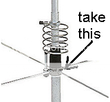
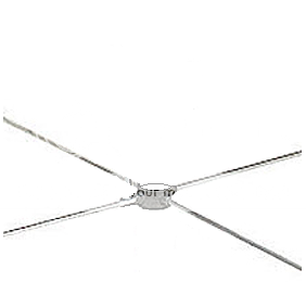
"yo franco, how bout you go get me a tornado hub and radials"
"sure boss, what you gonna do with the hub and radials"
"what im gonna do is this franco, im gonna take the hub and radials, cut the radials in half and stick em on top"
"on top boss, i aint seen it done like that before"
"zactly franco, we gotta make it look different"
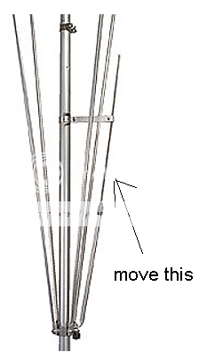
"franco, how bout you flip that gamma over so we dont need an insulator and new hub"
" great idea boss will it work"
"sure it will work franco, all we gotta do is find the 50ohm tap up top and cancell the reactance with the gamma"
"boss your too smart"
"i know franco i know, thats why im the boss and your the builder"
"hey presto franco"
"boss that looks interesting and we got everything we need already, we can start building right away, what we gonna call it"
"what you think franco"
"i dont know boss, i aint never seen no antenna turned upside down with radials on top before"
"thats it franco, the name, we gonna call it the topone"
http://i5.photobucket.com/albums/y152/ukmudduck/how%20can%20i%20make%20these%20look%20interesting/heypresto.png[/QUOTE]
there it was lol...still great hihi...
Im hoping its center fed...although the tuning advice says "cut" the top..
So that leads me to think its end fed.
In aspect to the "source". Of course anyway can play a trick etc, and in all honesty..i think we have spoken before that they should do a center fed halve wave, so im not astonished it is there.
Back to the source...
Simon is a stand up guy...our paths have crossed several times..
And ill stand in the line of fire for him.
Some thoughts Eddie..
Did you place tip height equal ?..
Have you considered what to include as material loss ?
(Which material btw ?)
What is the choke amount ?
and..have you include the loss of the coax used ?
Have you thought about the velocity factor do to the antenna it self ?
As im reading something like fiberglass..
Never mind..i dont need answers...just things to consider..
O well..
It either is a t2tl or a sleeve dipole version....
Hoping for the sleeve dipole though..
And we need a higher power rating...i mean in all honesty....think logical..
if any manufacturer would use RG58 in a antenna...we would all complain.
But now we have "red type of coax" .and people find it "interesting"..
Obvious the colour...Red..those Italians hihi
Red ferrari..red temperament..red Ducati...Red..thats always a winner")
However RG58 in a matched load can handle the provided amount of power without issues.
But who knows maybe there is something else that limitates the power handling.
Really really ..hoping its a sleeve dipole version...and it has my vote
So that leads me to think its end fed.
In aspect to the "source". Of course anyway can play a trick etc, and in all honesty..i think we have spoken before that they should do a center fed halve wave, so im not astonished it is there.
Back to the source...
Simon is a stand up guy...our paths have crossed several times..
And ill stand in the line of fire for him.
Some thoughts Eddie..
Did you place tip height equal ?..
Have you considered what to include as material loss ?
(Which material btw ?)
What is the choke amount ?
and..have you include the loss of the coax used ?
Have you thought about the velocity factor do to the antenna it self ?
As im reading something like fiberglass..
Never mind..i dont need answers...just things to consider..
O well..
It either is a t2tl or a sleeve dipole version....
Hoping for the sleeve dipole though..
And we need a higher power rating...i mean in all honesty....think logical..
if any manufacturer would use RG58 in a antenna...we would all complain.
But now we have "red type of coax" .and people find it "interesting"..
Obvious the colour...Red..those Italians hihi
Red ferrari..red temperament..red Ducati...Red..thats always a winner
However RG58 in a matched load can handle the provided amount of power without issues.
But who knows maybe there is something else that limitates the power handling.
Really really ..hoping its a sleeve dipole version...and it has my vote
Anyway..would you happen to know if it is central fed or end fed ?...
Hoping it is central fed as that could actually bring something, and its not another end fed have wave.
I don't know for sure, but I figure it is center fed. I made the model center fed like the 5/8 wave.
Interesting that the specs state "tunable from 27.2 - 30 MHz. Apparently only covers 1/2 the CB band.
The original Gainmaster is tunable from 25.5 - 30.
I don't get it either 71. The article looks like a Sirio catalog and shows the radiator length is 16.5' feet. It also says it is tunable by cutting. With my model set at 16.5' feet the resonance is 28.000 mhz, so we probably don't want to be cutting anything on this one, but the words are there.
I would imagine that it is center fed, although I imagine there will be some wizardry beyond just being a T2LT antenna inside a fiberglass tube.
I agree...Sirio will likely have more words to say.
Eddie, those antennas are at the same mounting height as opposed to tip height right?
Same mounting height. I took my 5/8 wave GM model and made the radiator 16.5' feet, leaving the heights the same.
I'm not sure on the validity of this as of yet as every report references the same site.
I remember early on that the original GM word was passed on by Shockwave in the beginning too. We'll see.
As I noted above the 16.5' foot radiator seems very short, and is resonant at 28 mhz. My model shows a very narrow <2.00:1 Bandwidth. I don't know if tuning this antenna will make it broader in Bandwidth.
Im hoping its center fed...although the tuning advice says "cut" the top..
So that leads me to think its end fed.
Good point. It seems to me if you cut the top of a balance center fed dipole you would upset the balance. I'm still concerned about the 16.5' foot length however.
Simon is a stand up guy...our paths have crossed several times..
And ill stand in the line of fire for him.
I agree.
Did you place tip height equal ?..
Have you considered what to include as material loss ?
(Which material btw ?)
What is the choke amount ?
and..have you include the loss of the coax used ?
Have you thought about the velocity factor do to the antenna it self ?
As im reading something like fiberglass..
Never mind..i dont need answers...just things to consider..
The model has both antennas at the same mounting height of 36' feet.
I made the model with copper wire and it does not have a choke. I isolated the mast from the bottom of the antenna instead.
I did not add any coax loss to the model, I figure at only 16' feet it probably doesn't matter much...same with coax Velocity Factor.
It will be interesting to see how they get this thing to tune from 27.2 to 30 mhz and not unbalance the antenna.
Eddie,
I would not be too concerned about the 16.5ft, the wire in gainmasters has insulation and its housed inside a grp tube both of which slow the velocity of propagation,
You have been telling us for years there is nothing special about 5/8waves,
I was not convinced of that until Henry educated me, up to that point I sort of believed the BS that 5/8wave antenna builders promote,
5/8waves only have a gain advantage at low angles due to their extra 1/8wave of height of current maxima if the loss in the matching is equal in both antennas,
when mounted at the same tip height the 1/2wave has a small advantage over the 5/8wave,
stick that 1/2wave gainmaster at the same tip height & let us hope the 1/2wave gainmaster has the same magnitude of matching loss as the 5/8 version.
I can't say I know Simon, and before a week or two ago when I saw him post on another forum I can't say I've ever seen or heard of him before. The fact he put an add on said site he posted that on is a step in the right direction...
You can tune a "center" fed antenna by cutting the tip. Being a vertical, it would be impossible to get to be truly balanced anyway as the earth below will affect the lower element more than the upper element. In the case of a vertical, if you want to keep such an antenna as balanced as possible, height is might. Still, height wouldn't be enough to counter the imbalance brought on by simply using different diameter elements for the top and bottom sections (coax shield on the bottom vs a single wire on the top). Further, the feed point being slightly off center won't have much of an effect on the antenna anyway. It is how most people tune T2LT antennas as well, and they have worked very well for many people. All moving the feed point slightly off center will do is slightly raise the feed point impedance, and the distances we are talking it will be a slight difference, and not even noticeable.
The choke that is shown in the add points to a center fed design, does it not? Or at least a design where common mode currents will be significant. Assuming it is a center fed design, and it is limited to 500 watts (according to the add), and the fact it is a few feet shorter than a full length half wave antenna, I would think that they have some form of matching system built in to the design somewhere. The full length Gainmaster used a coaxial capacitor and a stub on its center fed design. I think that if it was something other than a center fed design they would have called it something else...
That being said, the fact that you may need to trim an element to tune the antenna may actually point to an end fed design...
The DB
More Exciting product from Sirio:
Performer 5000 LED - light up when you TX
Performer 2000 -- High power Handling, slick design
Gain Master Half Wave - 500W continuous, 1000W PEP
Stay tuned for more update soon!
Performer 5000 LED - light up when you TX
Performer 2000 -- High power Handling, slick design
Gain Master Half Wave - 500W continuous, 1000W PEP
Stay tuned for more update soon!
DB,
i would be surprised if it was not center fed, i hope its not like the a99 setup,
Simon is well known for his news & reviews on this side of the pond,
he knows the folk at sirio,
can you explain your few feet shorter than a full 1/2wave comment ?. you have me scratching my head.
I don't know where they get their power ratings from, in my experience the gainmaster won't stand 320w for long overs without the vswr creeping up,
The company that makes the red coax does the same stuff in black which would look a lot better / more professional.
Last edited:
dxChat
- No one is chatting at the moment.