

After years of promising myself I'd update our discontinued 1990s PLL synthesizer I finally have a solution I can use. Troy Radio sells a handful of DDS solutions, but one of them is a bona-fide screaming bargain. Their "AM/FM-only" package provides a rotary encoder, nominal 1-inch OLED display, the Si5351 DDS pcb and a motherboard with an Arduino pro-mini controller and hookups for roger beep, clarifier, scanning and a voltage regulator. Plus a package with enough wire to hook them all together.
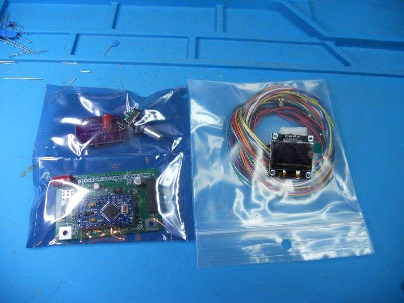
It lacks a way to "offset", or shift frequency for sideband modes. And they sell it for fifty-five bucks. Winner, winner chicken dinner!
Okay. Hence the AM/FM-only tag. The Browning Mark 4A transmitter uses the same internal carrier frequency for all three modes. No need to tell the channel synthesizer what mode you're in.
Check.
The Tram D201A uses the same carrier frequency for AM and LSB. To use USB you'd need to do some arithmetic to subract 3 kHz from the displayed frequency. But to use USB on 11 meters you need to learn espanol first, so I'm ignoring that tiny drawback.
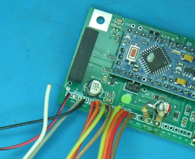
But it's not all smooth sailing just yet. The holes on the edge of the motherboard are tiny, spaced at 2mm. None of that bulky 1/10-inch spacing stuff here! I'm not fond of soldering stranded wire this thin to a circuit-board hole. The solder wicks up into the strands and creates a brittle point where the solidified strands meet the still-separate strands. Already broke one wire off the DDS connection before putting it into a radio.
My solution is JSC plugs and headers. Just one problem. They won't fit side-by-side. The sets of holes for each module are too close together.
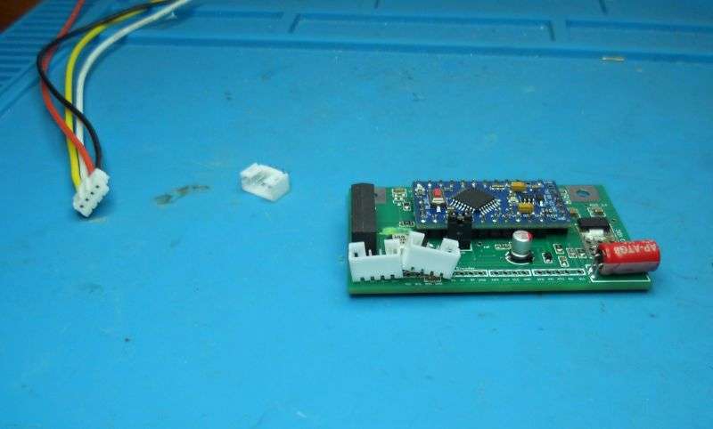
Staggering them top/bottom takes care of this. I'll be mounting the motherboard perpendicular to the mount surface with right-angle brackes, so this will work.
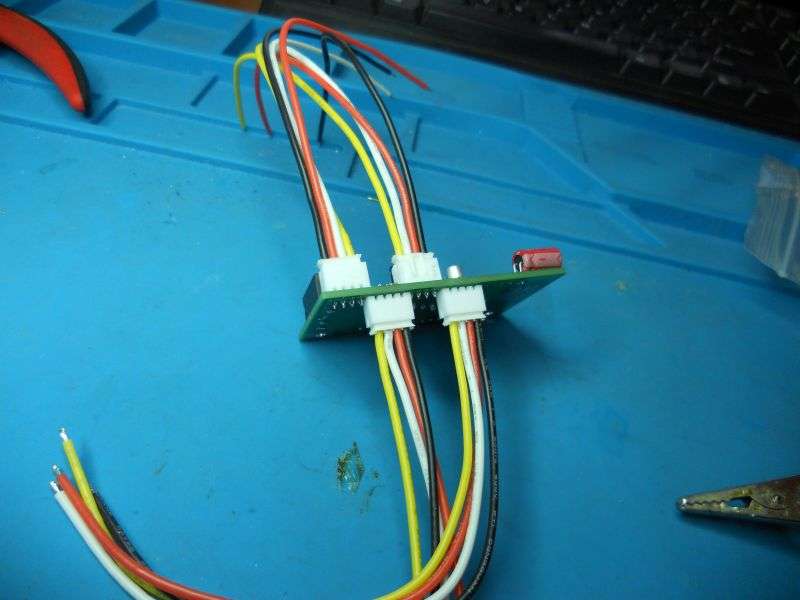
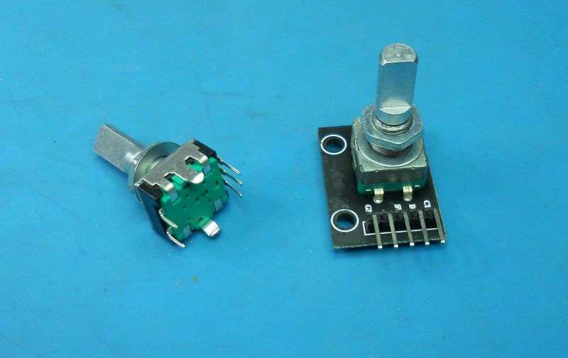
One other change. The rotary encoder is supplied naked. You can lap-solder five wires to the pcb pins, but I prefer connectors. The one on the left comes with the package. The one with the pc board and header pins is a generic fleabay item.
This is a work in progress. The first one of these goes into a Browning Mark 4A transmitter. The two 10k resistors scabbed onto the motherboard are taking the place of a clarifier. Don't need it on that application. The original D201 clarifier control should hook up and work like it's meant to.
Film at 11.
73
It lacks a way to "offset", or shift frequency for sideband modes. And they sell it for fifty-five bucks. Winner, winner chicken dinner!
Okay. Hence the AM/FM-only tag. The Browning Mark 4A transmitter uses the same internal carrier frequency for all three modes. No need to tell the channel synthesizer what mode you're in.
Check.
The Tram D201A uses the same carrier frequency for AM and LSB. To use USB you'd need to do some arithmetic to subract 3 kHz from the displayed frequency. But to use USB on 11 meters you need to learn espanol first, so I'm ignoring that tiny drawback.
But it's not all smooth sailing just yet. The holes on the edge of the motherboard are tiny, spaced at 2mm. None of that bulky 1/10-inch spacing stuff here! I'm not fond of soldering stranded wire this thin to a circuit-board hole. The solder wicks up into the strands and creates a brittle point where the solidified strands meet the still-separate strands. Already broke one wire off the DDS connection before putting it into a radio.
My solution is JSC plugs and headers. Just one problem. They won't fit side-by-side. The sets of holes for each module are too close together.
Staggering them top/bottom takes care of this. I'll be mounting the motherboard perpendicular to the mount surface with right-angle brackes, so this will work.
One other change. The rotary encoder is supplied naked. You can lap-solder five wires to the pcb pins, but I prefer connectors. The one on the left comes with the package. The one with the pc board and header pins is a generic fleabay item.
This is a work in progress. The first one of these goes into a Browning Mark 4A transmitter. The two 10k resistors scabbed onto the motherboard are taking the place of a clarifier. Don't need it on that application. The original D201 clarifier control should hook up and work like it's meant to.
Film at 11.
73
