• You can now help support WorldwideDX when you shop on Amazon at no additional cost to you! Simply follow this Shop on Amazon link first and a portion of any purchase is sent to WorldwideDX to help with site costs.

Older Connex 3300HP-ZX mod identification?

JDE

New Member
Feb 9, 2022
77
20
8
38
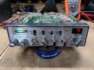
Just had this Connex 3300HP-ZX hit my bench. This was actually the last radio my father in law used before he stopped driving some years back. He passed away 2 years ago, so this radio has great sentimental value to me and will be going in my pickup. Already cleaned the faceplate, knobs, front chassis area, mic port, 3.5mm jacks, knob pots, and replaced the burnt out bulb in the meter with a white LED.

It does transmit. Low = 2w deadkey, swings 15~. High = 6w deadkey, swings 20~. This is on a Bird43 and 50w slug, no other meter to compare to at the moment, and I've never had this Bird aligned so it may be off a bit. Sounds great on my nearby monitoring radio, a 20~ year old General Lee that is aligned.

It also receives well from that same General Lee, clean and clear for the most part. It has a bit of static crash, and that's standing back from my workbench not touching or bumping the radio at all, volume 25%, RF gain up, AM/High Band D/any channel. Didn't seem to affect the quality of receive, though.

The two transistors on the right side of the chassis(audio amps?) do seem to run warm. Driver and finals get a little warm after TXing for a while, not unexpected, and this was in a 80-90f garage.

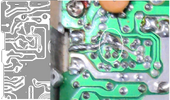
I'm still very much learning the ropes here so I'm trying to figure out what mods, if any, have been done to this radio. In the component side photo, top right, to the right of the DC filter cap you'll see two diode/resistor combos(don't have PCB numbers on those yet), doubt those are factory. There have also been some caps replaced on this radio. This thing probably saw a truck stop repair guy once or twice in its life.

Also wouldn't mind some schematics/mod info/etc. One cbtricks mirror site doesn't have anything for this radio(cbtrickz), and the other mirror site has been down for weeks(robco). Pictures attached. Thanks!
 

Attachments

  • My_3300hpzx_001.jpg
    My_3300hpzx_001.jpg
    286.7 KB · Views: 42
  • My_3300hpzx_002.jpg
    My_3300hpzx_002.jpg
    2.1 MB · Views: 52
  • My_3300hpzx_003.jpg
    My_3300hpzx_003.jpg
    2.2 MB · Views: 45

CX33 Talkback mod.jpg
"Talk Back" increase (and makes it clearer) mod. Similar to the way I used to do them. not sure what value they used, though. This mod is OK.

CX33 TR32 missing part side.jpg
TR32 missing. No AMC control, if this is removed, except to now manually adjust the Mic Gain back to about 9 O'Clock to keep from distortion (causing Bleedover in other's receive).

CX33 TR32 missing solder side.jpg
TR32 pads on the solder side. At least they soldered the holes over.

2SC945 is the part number for this.

CX33 Super Whack Pack mod.jpg
"Super Whack Pack" mod. I bet it has "Box Cars" on TX on the Oscilloscope. Especially with TR32 missing.

CX33 Super Whack Pack mod solder side.jpg
Solder side.
 
On the inside it's pretty much a Galaxy DX33HML with a different name badge. The ID number on the front edge of the circuit board isn't terribly clear in the pic, but looks like "EPT3600-14C". This was the last revision before the lead-free rules kicked in.

It's documented here, along with the prior "B" version of that circuit board.

http://73.235.100.209/radios/galaxy/dx33hml/index.html

73
 
You could pull out TR53 and move it to the empty TR32 spot. TR32 has two limiting functions, TR53 is used for only one of the two. Installing TR32 will allow the mike amp to hold its own output below the distortion level, even though the AM mod limiter will still be missing.

A lesser evil if you don't have a spare 2SC945 transistor on hand to pop into TR32.

73
 
Either one will disable the AMC, I used to see 5, 6, 7 components cut/clipped or even missing. You ae referring to the positive peaks of the Mic preamp (IC4) getting "clamping" feedback on positive going voltages through D67, D68 and D69.
Once the chain is broke, beginning, middle, or end of the chain, the dog gets loose.
 
It is derived from the original Cobra 148GTL-DX Mark II (PB-010AB), with an MC145106 PLL in it.
Yes, I am familiar with it and all Galaxy/Connex/Mirage/Ranger et al... variations since then.

CX33 AMC Positive and Negative reacting paths.jpg
Also, where D70/R176/R177 come together, D71 comes in from that top line from +8v RX to disable/clamp the Mic input when in RX.

You mean these 2 paths?
I have seen R246, TR53, D83, TR34, D70 and TR32 either cut or removed, in any combo thereof. And other components too. They all copy each other.
 
Last edited:
  • Like
Reactions: Eldorado828 and JDE
A lot of awesome info, thanks guys. 2 of the 3 cbtricks mirrors that are still online both appear to have the same info, and it's actually quite a bit compared to most of the other radios I've looked up on there. That's great, lots of reading to do now haha.

For TR32, I'd like to get it replaced rather than steal it from elsewhere in the radio, since the goal is to get this thing back to oem-complete and fully functional, then put it in the pile of radios waiting on me to learn how to do alignments. I checked digikey and the only 2SC945 they have are all marketplace listings(third party seller) and they're a buck a piece. eBay has them cheaper, but quality comes in to question there. If the Cobra 29 NW ST has one, then I have 2 of those radios to use for parts since they were beyond repair.
 
Last edited:
Something interesting on this EPT360014C board. TR32 is mislabled, it says TR37 which you can kind of make out in my component side photo. Just below and to the right is the real TR37 which is labeled properly. Noticed when I went to populate TR32 and had to come back to see the photos and replies, and pull up a board layout diagram to confirm I was replacing the right part haha.

I also noticed that my TR5 and TR52 are swapped, compared to the Galaxy DX33HML EPT360014C board layout diagram. Also, my TR41 is TR47 on the diagram. Guessing I just have some slightly different revision of board?

I removed the double resistor+diode from R240, and according to the schematic a 560ohm goes there so I'll need to dig one up. The only mod I can find on google that touches R240 is the NPC-RC mod where you add a 1n4001 in series with the resistor there, but I had two resistors and two diodes. Why?

At this point the radio no longer transmits, I get the red TX light but nothing out at all. Not sure what R240 does but it being missing is probably why. The only other thing I touched was populating TR32 with a C945 from that parts radio.
 
I took the liberty of using the CB Tricks archive to help you with this....

1652630588307.png
Top of the board layout

1652630636999.png
Bottom Foil Side -

Note the foil traces for the graphic are colorized so you can insert the R240 properly and to the right holes.

When you reinstall the 560 ohm - you may also want to check and verify that the Mirror Board jumper - when you measure the voltage with that board installed - is between 5 to 5.6 volts - before you start your tune up.

Why does this matter?

Spurries and mixer results - too low in wattage because the voltage is set too low you may think you're going up but that may be from you fooling the meter.

The 5 to 5.6 volts easily gets you to the 4~5W meter scale reading and that is where you start the tune up - for the variable power the radio has - can upset the accuracy of where the wattage and meter reading needs to be.

Good luck on this project - wish your dad was still around to trade stories as you fix this beast, but now you have a lot of help here and the radio is in good hands, yours.
 

Attachments

  • 1652630609019.png
    1652630609019.png
    577 KB · Views: 8
Always good to hear from you Andy, and thanks for the info.

I got R240 reinstalled, a 29 NW ST parts radio happened to have it. That got me back my TX, but I have very little modulation, barely enough to move the needle in the meter or on my Bird 43. Still sounds good on my aligned General Lee sitting nearby.

At this point it seems I need to realign the TX section to undo whatever adjustments the last tech made when he installed the double resistor/diode setup at R240. One of the cbtricks mirror sites has this guide for TX alignment, guessing I just need to follow the instructions there?

http://73.235.100.209/radios/galaxy/dx33hml/dx33hml_trans_adj.html

The only frequency counter I have is a cheapie one from ebay that has an SMA connector. I'd need to whip up an RF sampler to use it, but this FC is just a cheap chinese kit I paid maybe 10 bucks for.

In the above TX alignment guide, what do they mean by modulation meter, deviation meter, and adjusting to100% modulation depth? I'm slacking on equipment since I'm still learning so all I have is a Bird 43, couple of DMMs, and a Sinadder 3 that I need to learn how to use.

Another issue I discovered is that the speaker doesn't work, jumpered in a known working speaker and still nothing. Foil side shows nothing out of the ordinary, no bad solder joints or broken traces in that area. I'll try to make my way through the schematic to figure that one out. Ext Speaker and PA Speaker jacks both work.

Last question, what is the mirror board?
 

dxChat
Help Users
  • No one is chatting at the moment.
  • dxBot:
    Tucker442 has left the room.
  • @ BJ radionut:
    LIVE 10:00 AM EST :cool:
  • @ Charles Edwards:
    I'm looking for factory settings 1 through 59 for a AT 5555 n2 or AT500 M2 I only wrote down half the values feel like a idiot I need help will be appreciated