• You can now help support WorldwideDX when you shop on Amazon at no additional cost to you! Simply follow this Shop on Amazon link first and a portion of any purchase is sent to WorldwideDX to help with site costs.

Older Connex CX-3300HP completely dead.

Bamalama

New Member
Jun 21, 2018
3
0
1
60
Hi, guys. I have an older model with the red channel display. (EPT360014B board) that will not light up at all. It's not blowing fuses, so something has opened up somewhere.

I could sure use a point in the right direction.
 

Have you looked carefully at the parts connected to the inside of the power jack?

There will be two small wire coils, called chokes, one attached to each outer pin on the inside of the power jack. The other end of each one solders the main circuit board.

A previous hookup with positive and negative wires reversed is supposed to blow the fuse. A diode is connected between hot and ground in the radio. When the polarity is correct, this part does nothing. Apply power in reverse and it becomes a dead short. Should blow the fuse, and also remain a dead short circuit from the stress. If the radio was powered in reverse with no fuse, those chokes will look crispy. The choke coil nearest the center of the radio is usually ground. Look at the foil side of the circuit board where it attaches. The foil can burn through and cut the circuit that way.

Bear in mind that if this is what made the radio go dark, the reverse-protection diode will likely be a dead short. It has to be removed to find out what other damage you may have. We won't power up a radio unless a good diode has been first put into a radio where we find this. Simply removing a damaged protection diode makes the radio vulnerable to real damage if the radio doesn't have one in it.

73
 
Thanks for the quick reply, nomadradio.
I'm familiar with reverse protection diodes. I've replaced my share of them.
There's no dead short and it's not blowing fuses. The chokes look to be in pristine condition. There are no burned or damaged foils on the copper side and no visibly crispy components, bulgy capacitors or anything else that might indicate excessive current.

I've done some sniffing around with a DVM and I can trace B+ voltage through the on/off switch to a TO-220 cased voltage regulator (TR41-A1869) and a smaller TO-92 transistor (TR40) , but no voltage *after* them.
I just downloaded a schematic of the Galaxy DX33HP (same board) so I'm going to work my way through it from the power socket.

It seems like something has opened up. Maybe one of those vregs.
 
I'm in the habit of connecting a current-limited 9-Volt "bench" power supply to the radio when we find a blown TR40. First question for me is, "what blew it out?" The center leg of TR40 comes loose, the negative end of the second power supply to ground, and the positive side to the foil pad where TR40 center leg was soldered. The foil trace along the very front edge of the circuit board is also a suitable spot to clip the positive-side 9-Volt gator clip.

If the radio runs okay without tripping the power supply's current-protection, fixing the 9-Volt regulator should bring it back to life. And if there is still some sort of overload on that section of the radio's power supply, it must be cleared first. Don't want to blow out the new TR40 first time you turn it on. At the very least check with a meter
for a short to ground on the foil pad for TR40's center pin, after TR40 is removed. If you read a short, don't try to fix the regulator before the short is cleared.

That regulator circuit does a fine job when it works, which is most of the time. But I refuse to fix it when it breaks. We use a 7809T 3-terminal regulator chip, like the ones found in the 2950 radios. The pins don't line up correctly, but still far less trouble than the stock circuit.

My experience with repairing failed voltage regulators suggests that you'll need to replace both transistors and the zener diode at a minimum. If you miss one bad part and power it up that way, it probably still won't work. The labor to take the circuit loose just to check those parts is a lot more than just dropping in the 3-terminal regulator chip.

And if you don't have a handy 'bench' power supply to try the smokeless test first, this makes using the 3-terminal regulator chip even more attractive. At least it has a current limiter built into it. The factory regulator circuit doesn't.

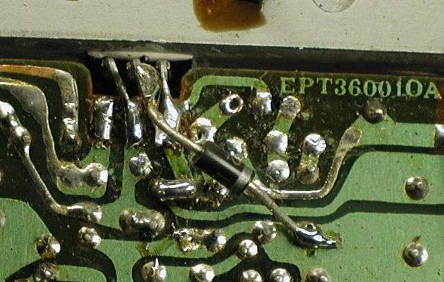
Here's a pic showing this tick using a 8-Volt 7808T chip with a diode in line between its ground pin and the circuit board's ground foil. Serves to bring up the output voltage a bit. Only a ground wire is needed in place of that diode if you use the 9-Volt version.

ept360010a9vregsubsm.jpg


73
 
  • Like
Reactions: Handy Andy
Thanks again for the prompt reply.

I'll try the test you describe and get back to you with the result soon.

I appreciate your help.
 

dxChat
Help Users
  • No one is chatting at the moment.
  • dxBot:
    Tucker442 has left the room.
  • @ BJ radionut:
    LIVE 10:00 AM EST :cool:
  • @ Charles Edwards:
    I'm looking for factory settings 1 through 59 for a AT 5555 n2 or AT500 M2 I only wrote down half the values feel like a idiot I need help will be appreciated