• You can now help support WorldwideDX when you shop on Amazon at no additional cost to you! Simply follow this Shop on Amazon link first and a portion of any purchase is sent to WorldwideDX to help with site costs.

omni ground elements effecting a beam below them

B

BOOTY MONSTER

Guest
on 27 MHz , are the short ground elements on a omni antenna like a sirio 2016 mounted a few feet above a flat side beam long enough to effect the beams performance enough to be detected by the typical user ?

and ...... how much do full size ground elements effect a horizontal beam below them ? does it help or minimize the effect if the omnis ground elements are 45 degrees parallel to the beams elements ? like a X over an H . HXH

BM here is a 5 element horizontal yagi that was a file attached to the Eznec 5 software. I modified it with a mast and added a simulated A99 with 4 horizontal radials sitting above the beam.

Note that there is a difference in the patterns, but it is negligible even though the antennas are close. I doubt anyone could notice the change in operations just as noted in these patterns.

There is a suggestion here that opposite polarity makes a powerful difference in antenna response, and in this case the A99 with radials above the beam is almost invisible.

Sorry I did not model all the options you note.

The radials are 1/4 wave and the A99 is about 6' feet above the beam. The beam is approximately 20' feet long and the only alteration I made to the beam was to add an insulated boom and a mast attached to the Earth. I did compare the beam's pattern between the boom and no boom and they were also very similar in gain and angle.

View attachment Five elem beam with A99 above.pdf

Here is the A99 pattern. It was somewhat ill affected by being above the beam, but it might not be much. I also include the wires view of this antenna setup.

View attachment Five elem beam with A99 w radials above.pdf
 
Last edited:
Well, until this spring, my friend had a 20 foot 1 3/4" black pipe, set up so 12 foot stuck out the top of a 50 foot tower. He had a Mosley TA-33 1 foot above the tower top. 10 foot above that, he had a Cushcraft 13B2 and the last foot he mounted an Imax 2000. Had to make adapters so the Imax and cushcraft fit the large diameter pipe, he worked for Caterpillar so it was a breeze for him (y) He ran that for a year with no difficulties and made contacts with all three antennas with great results.

One day we set up a 70 foot tower to the north end of his house, moved the Imax to the 70 foot tower, and installed a Diamond X510 2 meter / 70 centimeter vertical where the Imax was.

Again, always made great contacts.

I sent pictures of this set up to Moleculo, I do not have the pictures any longer, Mole may? Look for the pictures of Ron's antenna farm Mole.
 
Thanks for that info Marconi, myself and a friend are in the midst of reworking
our base's and i was contemplating using a maco 103 flat side with my 5/8 over top of it, as well as my friend who also has a 103 but wants to use his imax stacked over top.

I was not sure if they would cause problems between each other.


Lets say i stack my 5/8 with 4-5 feet of separation from each mounting point everything should be alright, and wont effect each other correct?

Thank you BM for posting this question.
 
Hello Guys,
To know sure how much a vertical antenna with radials would have interaction with a horizontal yagi below (and vica versa) you would have to model each situation.

Since not all can do that, it is fair to say in almost all cases the groundplanes will have (slight) negative infuence.

THE SOLUTION:

Make sure all or at least most elements of the beam are dc grounded to the boom.
If this isnt the case allready mechanical, you can short-circuit the center pieces of the elements towards the boom without getting into trouble.

Some manufacturers have the elements isolated on the boom, often the non-metal"clamps" are better in that way as elements tend to brake near the boom.
And there is a thing called boom-effect.
This is more important on higher frequencies, but what it comes down to is:
As soon as years go past, the electrical bonding between element and boom get less.
Therefor the optimum element lenght changes slightly. (but on 11 meters you would need to be really precise in order to measure this.)..
Now, if the elemenents are already isolated and optimised in that way, nothing will change.

Oke, back to that Vertical with radials ontop of a beam...(were at elements grounded at the boom)
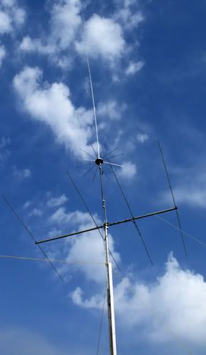
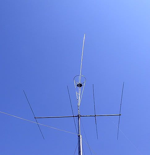
Then loose all the groundradials on the 5/8 wave and place the 5/8 wave just above the yagi.

The entire yagi will work as a "radials" wich is a better system them just 4 radials 3..4 feet long :)
You migth need to retune the vertical slightly.

Oke, then the imax/a-99 etc. kind of antennas can just be placed above the yagi without effecting the yagi in either way.
There is a slight advantage aswell since those antennas do get better with the additional "yagi-groundplane"- system.

@eddie, oke to be precise and i know you like to be...just some thougths for you:
Have you considered to model the boom as mechanical part of the antenna in this case.
Have you thougth of a split source in order to "feed".
antennas are 3dimensional and have many aspects. We could show a beautifull elevation pattern but the azimuth pattern migth be screwed. So you migth wanna take a look at that aswell.
Last thing here, but the first to take a look at is the SWR of the beam and how that is influenced.
The first indicators there is something "wrong" is the SWR. A good example is the vertical beam attached to a metal mast, that often gives SWR problems..without modeling you know the antenna has some issues.

Kind regards,

Henry 19SD348
All about antennas
 
Last edited:
  • Love
Reactions: Alabama Buckeye
@ Eddie,

almost forgot something...
If you take a look at the elevation pattern you have provided of the antron there is a quite a difference in the higher angles. (left compared to the rigth side).
That is also a example of a pattern beeing disturbed.
The Rigth side has a angle of almost -2dB at a 45 degree angle.
For perhaps some E-skip this migth come in handy, but it is for true dxingof no use.
The angle does do something we do not want, and thats picking up lots of noise.
And thats something you do hear. So were not only looking for maximum gain..but how the entire system performance.

anyway, im off to do see some friends...equal to things other people do on a normal sunday...
Take care!

Regards,

Henry
All about antennas
 
Henry, I basically put a sibilance of an end fed 1/2 wave above the beam and added a mast, but had to insulate it from the AT to get Eznec to accept the input, so this whole exercises was just quick and dirty.

I just wanted to see if I could get the model to work and if either pattern went to hell in a hand basket with the AT's close together. This model in no way is meant to duplicate precisely such a setup, and I was surprised at the lack of affect that resulted.

I also did not take time to model the 1/2 wave by itself and at that height, but it looks pretty close I think. I did not tweak the models for SWR or resonance, but they both would need matching for sure. I do not know why the beam's pattern skewed as it did in the back only. However the vertical sits much closer to the reflector and that might be the difference for the beam. Maybe the mast and A99 needed to be set more to the middle of the boom and that might minimize the shewing noted, or the radials need to be shifted in direction...as BM suggested. That would be a lot of work I think.

This only suggests to me to not be too concerned with such a setup. I was pretty sure this is what I might find based on my personal experience with my 4 element horizontal with both an A99 - 1' foot above and a Starduster - 10' feet above, but I wasn't sure. As best I could tell, I did not notice any negative results with either setup.
 
Last edited:
Henry, I basically put a sibilance of an end fed 1/2 wave above the beam and added a mast, but had to insulate it from the AT to get Eznec to accept the input, so this whole exercises was just quick and dirty.

I just wanted to see if I could get the model to work and if either pattern went to hell in a hand basket with the AT's close together. This model in no way is meant to duplicate precisely such a setup, and I was surprised at the lack of affect that resulted.

I also did not take time to model the 1/2 wave by itself and at that height, but it looks pretty close I think. I did not tweak the models for SWR or resonance, but they both would need matching for sure. I do not know why the beam's pattern skewed as it did in the back only. However the vertical sits much closer to the reflector and that might be the difference for the beam. Maybe the mast and A99 needed to be set more to the middle of the boom and that might minimize the shewing noted, or the radials need to be shifted in direction...as BM suggested. That would be a lot of work I think.

This only suggests to me to not be too concerned with such a setup. I was pretty sure this is what I might find based on my personal experience with my 4 element horizontal with both an A99 - 1' foot above and a Starduster - 10' feet above, but I wasn't sure. As best I could tell, I did not notice any negative results with either setup.

i think you meant semblance not sibilance but whos counting.;)
 
Hi m8,

I know what you intended to do, you tried to help other forum members wich is appricated! Therefor my answer was only there to let you think.

But ill be more clear.
If you have problems to insert things in eznec, no worries..we all have.. a helping hand migthbe the solution. What you shouldn’t do is make a model and provide "proof"which because of the lack of input can be false.
You mention "here are the results of the antron and it is "ill" effected etc.

If you would have done things right you would have noticed the beam acts as a groundplane and the “strange” high angle elevation lobs would change of the antron.
How can you be surprised of the results and take your conclusions of a input which isn’t a replica of what is actually going on?
You intentions of only producing the model to see “if it could be done” seems the opposite of what is written above.

Now, we seem to have “conclusions” like: “it is negligible” etc. : You mention that it is no way this was intended to duplicate the “precise setup”…but further along the line we follow you to your conclusion: “not to be concerned with such a setup”. That’s a bit strange in my ears..

By giving such “conclusions” is exactly the point where things go in the mist.
We have SP22 now saying “oke, so its oke to go ahead with the radials 3..4 feet above the antenna?” What he should do is loose the radials and place the vertical directly above the yagi so that the yagi performance as a the radial system..he would have been better of. Don’t forget you are a forum member with respect, people lissen to you..

I don’t believe you when you say: This is the best you can tell, you know better.

Did you realize the higher lobs only produce a high noise level. That’s nice isn’t it…a a-99 on top of a beam with s9 qrm…we are not waiting for that

I can promise you: if you put up a antenna with ¼ wave radials above a beam it is going to be a problem, a drop of a couple dBs in forward gain and a drop of impedance are easily seen. And im not talking “worst case” secenario here. Ofcourse shorter radials might be no problem, each situation should be verified. There are situations where you just cant “match” the beam anymore.

Your thoughts on the antron moving it forward or backward on the boom is a dead end. The vertical will have a 90 degree shift in its electro/magnetic field compared to the horizontal hence the vertical/horizontal polarization. Further more the antenna is situated on the current bow of the radials, we can attach almost anything there…take for example the boom of a antenna, have you ever considered that strange piece of metal between the elements (boom) ..and how it is possible that it has or does not have influence..

If one insisted on using a antron with radials above a beam (couldn’t tell you why though)..then it might be something to look into it. Though I wouldn’t as it will also bring along mechanical problems. So perhaps we have a briljant solution wich can not be made in the real world.

Conclusion:
A beam with the elements grounded to the boom will provide a good groundplane system. Infact it can be better than most commercial vertical antennas with a radial system underneath it. It is in such a case a good option to drop the original radials.
A vertical with the original radials attached can (doesnt need to) provide serious problems when placed above a beam.

Kind regards,

Henry 19SD348
All about antennas
 
I tried this very setup:

4516.jpg


I found the Yagi had no problems with the vertical w/short GPS about 5 feet above, but the short GPs made for inferior performance compared to what I'd experienced with full length radials on my 5/8 wave antennas.

I removed the GPs as suggested and lowered the 5/8 within a foot of the Yagi. The severe storm system we experienced came through and I removed the 5/8 without an opportunity to compare the setup in this way. I had been redoing the Qv4k in the meantime and put it up in the air above the Yagi instead right above the Yagi. Both still perform very well:

4889.jpg
 
I can promise you: if you put up a antenna with ¼ wave radials above a beam it is going to be a problem, a drop of a couple dBs in forward gain and a drop of impedance are easily seen. And im not talking “worst case” secenario here. Ofcourse shorter radials might be no problem, each situation should be verified. There are situations where you just cant “match” the beam anymore.

Your thoughts on the antron moving it forward or backward on the boom is a dead end. The vertical will have a 90 degree shift in its electro/magnetic field compared to the horizontal hence the vertical/horizontal polarization. Further more the antenna is situated on the current bow of the radials, we can attach almost anything there…take for example the boom of a antenna, have you ever considered that strange piece of metal between the elements (boom) ..and how it is possible that it has or does not have influence..

If one insisted on using a antron with radials above a beam (couldn’t tell you why though)..then it might be something to look into it. Though I wouldn’t as it will also bring along mechanical problems. So perhaps we have a briljant solution wich can not be made in the real world.

Conclusion:
A beam with the elements grounded to the boom will provide a good groundplane system. Infact it can be better than most commercial vertical antennas with a radial system underneath it. It is in such a case a good option to drop the original radials.
A vertical with the original radials attached can (doesnt need to) provide serious problems when placed above a beam.

Kind regards,

Henry 19SD348
All about antennas
I think Henry pretty well nailed it. I think he can be considered an 'expert witness' since he is an antenna builder/mfr. Specializing in beam antennas in particular.

His conclusions may be of interest to BammBamm's consideration: to put a Sirio 2016 above a horizontal beam. Which is what originally what inspired Booty's thread here.

From what I can gather from Henry's explanation, the 2016 with the short radials might be possible to use if it is high enough above the horizontal beam. But as for regular length ground planes (1/4 wave length) above a horizontal beam; it would vastly affect the beam's performance, tune, and lobe characteristics.

Personally, with so much at risk (affecting both antennas to various degrees) for the amount of work and expense involved, I would do it with a Imax/A99 w/o radials above a horizontal beam. But that is about it.
 
Last edited:
hey henry , what do you (or others) think about using a sigma/vector type antenna like homer is using above his 4 element beam ?
 

Attachments

  • 4889.jpg
    4889.jpg
    208.7 KB · Views: 57
I think Henry pretty well nailed it. I think he can be considered an 'expert witness' since he is an antenna builder/mfr. Specializing in beam antennas in particular.

His conclusions may be of interest to BammBamm's consideration: to put a Sirio 2016 above a horizontal beam. Which is what originally what inspired Booty's thread here.

From what I can gather from Henry's explanation, the 2016 with the short radials might be possible to use if it is high enough above the horizontal beam. But as for regular length ground planes (1/4 wave length) above a horizontal beam; it would vastly affect the beam's performance, tune, and lobe characteristics.

Personally, with so much at risk (affecting both antennas to various degrees) for the amount of work and expense involved, I would do it with a Imax/A99 w/o radials above a horizontal beam. But that is about it.

or perhaps the sirio gainmaster, no gp radials either.
 

dxChat
Help Users
  • No one is chatting at the moment.
  • @ Wildcat27:
    Hello I have a old school 2950 receives great on all modes and transmits great on AM but no transmit on SSB. Does anyone have any idea?
  • @ ButtFuzz:
    Good evening from Sunny Salem! What’s shaking?
  • dxBot:
    63Sprint has left the room.
  • dxBot:
    kennyjames 0151 has left the room.