• You can now help support WorldwideDX when you shop on Amazon at no additional cost to you! Simply follow this Shop on Amazon link first and a portion of any purchase is sent to WorldwideDX to help with site costs.

Palomar 300A black face amplifier

Unit 75

"TRAINMAN"
Jul 29, 2014
530
1,032
153
Central Alabama
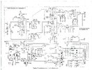
Had a customer drop this amp off to me saying it just stopped putting power out. He told me it was all re-capped. I found a 22uf 35v cap on the 2X 6KD6 driver board that blew the positive side rubber right out. It was an original that had not been replaced I replaced it with a 22 uf 50v cap. The other problem I found was with a 468 trimmer compression cap that mounts behind the low/ high power switch. It is completely dead...does not measure..even after turning it. Here is my question. The schematic shows the variable capacitor symbol but it does not have a value beside that. Does anybody know what value this 468 should be set at? I have a new one to put in. Thank you
 
Last edited:

I'm going to take a guess based on the information available to me, but keep in mind that I am not a tube guy, I only daydream about being one. This just looked like a fun thing to try figuring out.

The datasheet for the 6KD6 tubes says the transconductance is .014 siemens. Two tubes in parallel should give 1/(.014*2)=35.7ohm input impedance.

I don't know the size of that inductor, but I am going to guess it should be 180nH for 11m, which would put the variable cap at 82pF. Since this is a multiband amplifier, that inductor is probably not 180nH.

Now to wait for someone that actually knows to chime in to see if I was close lol.
1776807426379.png

1776806839225.png
 
Schematic's wrong. The compression trimmer soldered to the High/Low switch is the input-impedance matching adjustment for Low side. This amplifier does something out of the ordinary. The Low side feeds the radio drive directly to the four final tubes. You can remove the two driver tubes and still use the amplifier's Low side just fine. The trimmer under the driver tubes is the input adjustment for High side only. The schematic fails to capture this detail.

73
Did the schematic also miss an inductor on the low side then? Should be about 18Ω looking into those 4 tubes. Hard to match 50 to 18 with just a cap.

Edit: or is the trace/lead inductance enough? 150pF and 150nH gets it close.
 
Last edited:
The 468 trimmer cap on the input to the driver tubes is just below the input coil on the schemo. Isn't marked or identified. Pretty sure it's 5 or 6 turns on a half-inch inside diameter.

73
 

Attachments

  • 300A.JPG
    300A.JPG
    497.9 KB · Views: 4
I don't want my education to take away from the original question, but are you saying there is also a trim cap on the low side of the switch like this
1776833102487.png
 
Almost. The coil is across the two low-side lugs of the switch, not between the switch and the final cathodes. And the output from the driver PI-net coil goes to a High-side lug, not to a common lug. I drew it up years ago and plastered it over the factory schemo's High/Low switch. Haven't seen that copy of the diagram since we started using a desktop box for documentation decades ago. I'll scan it if I can find it.

Oh, and yeah. I think the max capacitance of a 468 is around 500 pf.

73
 
Last edited:
  • Like
Reactions: brandon7861

dxChat
Help Users
  • No one is chatting at the moment.
  • @ Spanish:
    Where do i upload schematics
  • @ BJ radionut: