• You can now help support WorldwideDX when you shop on Amazon at no additional cost to you! Simply follow this Shop on Amazon link first and a portion of any purchase is sent to WorldwideDX to help with site costs.

Palomar 300A Black Face

357

Walkin' the dog
Sep 12, 2009
1,403
774
123
50
Chilliwack, BC
www.youtube.com
I picked up this amp today, it cleans up real nice.
The ceramic caps on the final plate look kinda toasted so I'd like to replace them.
Anyone know the values?
They say 3300M, theres 4 and the schematic says .0022 but no voltage rating.
If I had to guess, it looks like mine comes out to .0033?

This 300A has the HV relay on the bottom, is it a early version?

Also it has 6KD6's and 1 driver getter dont look too good but it has side and top getters, and the tops look good.
Should I be worried? I was told to get worried if its white....

I got the clamshell packing with it, I was told its been sitting for over 25 years.


IMG_1331.JPG IMG_1332.JPG IMG_1333.JPG IMG_1334.JPG IMG_1335.JPG IMG_1337.JPG IMG_1338.JPG IMG_1339.JPG IMG_1340.JPG IMG_1341.JPG
 
Last edited:

Wow, no way to test the tubes? Pretty risky.

Kinda like russian roulette.

This thing is nearly forty years old. If it had only 500 original miles, it might still run okay. All six tubes might somehow still be okay. Testing them can reduce the risks of a bad tube damaging the amplifier.

The question I ask someone who carries one of these in the door is "Do you want to sell it or keep it?"

Simply patching up what's broke today will be cheaper than catching up the last four decades' worth of predictable maintenance issues. A guy who just wants to flip it will only care if it works long enough to demonstrate and collect the money. The stuff that goes bad tomorrow or next month is not his problem.

But if he says he wants to keep the thing to use, this means he wants some reliability.

That costs more.

All five electrolytic caps MUST be replaced. They are a nonstop breakdown hazard. If any of them fails, it will usually overload the rectifier that feeds it. Sometimes the foil traces on the circuit boards will burn and lift from the pc board when the low-voltage caps fail. If the 12-Volt DC filter goes bad, it can take out the keying circuit and preamp. Although the preamp is probably already blown. This is NOT an option, ALL FIVE electrolytic caps have to go.

If the plug-in relay is good, that's cheaper. At least it just plugs in if you need to replace it. A forty-year old relay MIGHT still be okay.

Might.

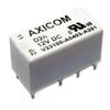
The two square white sealed relays are almost certainly no good. The Potter and Brumfield type number R50-E2-Y2-12VDC was discontinued and tends to cost thirty, forty or fifty bucks each.

An alternate number is AZ-931, the brand American Zettler. Pretty sure that one is no longer made.

You only need one of these for transmit side. The other one is for the receiver preamp. It is best replaced with a wire jumper across the two holes for the common pins. This will prevent the receive side from dropping out when that relay loses its standby side.

You can haywire a DPDT 12-Volt relay to replace a bad R50. Takes more labor, but you can use a cheaper relay. Just a tradeoff between parts cost and labor cost.

The band selector is a fraud. They included it to pretend that it was a legal ham amplifier. When the ham-linear rules were tightened in 1979, they had to stop making this model.

What makes it a fraud is the input side. The input-matching circuit for low side is soldered to the High/Low switch. The one for high side is under the driver tubes. These can be tuned for 10 meter ham, or for 11 meters, BUT NOT FOR THE OTHER BANDS...

THERE IS NO INPUT CIRCUIT FOR THE HAM BANDS, only tuned output circuits for those bands. Like I said, a fraud.

Jumping around the band selector removes the risk of arcing and/or cutting out. The band switch itself is a failure risk after 40 years.

The driver coil just gets removed altogether. A coil made from #12 wire, five turns of 3/4 in. diameter goes from the driver plate-tune cap to the coax that leads to the High side of the High/Low selector.

One small thought there. That piece of coax from the driver to the High/Low switch runs alongside some hot tubes. I have seen it melt and short internally. We learned to just replace it with a piece of the small teflon coax rather than wait for it to fail.

The 10-meter final coil is pretty much okay the way it is, just with the band selector and ham-band coils disconnected.

You may have noticed that there are no parasitic chokes visible on the plate-cap connections to the tubes. The bare wires on the plate-cap clips originally each had a tiny black ferrite bead slid over each wire. This trick works okay, but only until the ferrite bead gets hot, cracks and falls off. When this model was being sold new, we found that the beads were usually good for a month or two, tops before they cracked and fell off.

These were a way for Palomar to skip the labor to wind wire around resistors.

Any proper repair includes six of the conventional 47-ohm (or so) 2-Watt resistor with four turns of wire around it. One to connect each plate-cap clip to the plate choke for that stage.

But you'll probably just cross your fingers and try it the way it is, without installing parasitic chokes.

Russian roulette, but at least it's a game that gets played on your nickel.

The big relay underneath simply shuts down the high voltage to the tubes during standby. Later models eliminated this relay. Instead, they would switch off the cathodes of the tubes, breaking the ground side of the tube circuits to shut them down on standby. The later-production 300A that used a plug-in circuit board with 3 relays on it used this method, and did not have the large relay underneath.

Those are the predictable highlights of a 40-year tuneup on the 300A.

One last thought. NEVER mix and match the transformers for this model. Not even just to "test" it and see if it works.

Palomar used two different transformers. They both look IDENTICAL. But one of them supplies 280 Volts to a full-wave doubler circuit to get 800 Volts DC.

The other version feeds TWICE that voltage to a full-wave bridge circuit. There is no way to identify which HV circuit will be found in the RF deck without removing the bottom cover and having a look. The doubler circuit uses four 3-Amp rectifier diodes. This is what you have.

The other version has a small rectangular epoxy-block bridge rectifier module.

But until you remove that bottom cover and have a look, you don't know which transformer is the right one for your RF deck.

The transformers are NOT marked in any unique way that will reveal which one you have. We'll skip methods for identifying which is which for now.

If you mismatch transformer and RF deck one way, you have a linear that's always on "low" side, no matter which way you flip the High/Low switch. This is because you'll only get 400 Volts to the tubes this way.

Mismatch it the other way, and BLAM! first key. 1600 Volts blows the filter caps to bits. And the rectifiers.

Yet another round of russian roulette.

Oh, and yeah. Those disc caps. The dark spot is probably just from heat radiated onto it from a hot tube. If they don't check shorted, they are probably still okay.

But those are the highlights. With any luck you won't find a lot of high-mileage issues to go along with the age issues.

73
 
Last edited:
Thank you Nomad, very good info as always!

I'm gonna burn in the tubes for 24 hours then if I can get ahold of a tube tester, test them.
I tested the caps and resitors, all check spot on.
I cant really reform them without keying the amp cause of that relay so I'm kinda stuck there.

I still have the beads on the driver but I think I will take your advice and make some proper ones....should I do all 6?

This unit does have 300VAC on that relay, I dont dare key it yet.

I'm really in a pickle for cash, not sure if I'll play russian roulette or not.
suicide-1.gif

I cleaned all the relays (2) I could and was suprised they were in very good condition.

I did a 650KM round trip to get this amp and I'm in it for 250CAD including fuel.


Guess I got some desicions to make. :(


Yeah, I do. It's the dreaded "Little arcs across worn-out relay contacts" problem. I don't know just exactly why the 300A in particular is so likely to do this. I have seen it over and over. The relays in this amplifier are closing only partway because of wear and tear (and age). This causes a small, blue arc to jump across this small gap between the contact points. The RF energy in this arc gets amplified by the tubes, and causes a lot of RF power to appear between the driver cathodes and ground. So what, you say? That's where the transmitter is tied in, to those driver cathodes. This creates the rare, but famous and legendary "Back-Feed" literally jumping out of the amplifier back upstream into your radio final.
It doesn't have to do this for very long. One thousandth of a second is plenty long enough for this excess RF voltage to exceed the breakdown rating of a 12-volt RF transistor like a 2SC1969 or 2SC2312. The final's base resistor and/or bias circuit can get sideswiped along with the final.
Watching the output of this 300A on a 'scope (using a tube radio to drive it) will usually show a fuzzy trace briefly at key-up, revealing a short burst of arc on one or more of the relays.
You didn't say which version 300A you have. The one with three identical relays on a plug-in circuit board behind the meter is a real pain. The R10-E3604 relay was made custom, and became unavailble when RF Parts finally ran out of them about 10 years ago. We use a more mundane relay sold by Rat Shack and others, using wire jumpers soldered to the relay lugs, and routed to the correct PC board hole. Pretty annoying. The Rat Shack DPDT 10 Amp 12 Vdc relay is rated at 10 amps, and should last a while, at least.
The later version has the relay circuit board soldered in, bolted to the deck beneath the meter. The plug-in relay R10-E1-Y2-12Vdc is pretty generic, made by lots of competitors and sold a lot of places, like Mouser. The two little square, short white or yellow plastic relays that are soldered down are expensive when you can find them. Candyman used to have a generic substitute made by "American Zettler" with a number that started "AZ-931". An outfit called "Master Distributors" had some Potter and Brumfield R50-E2-Y2-12VDC like the originals for $35.00 EACH last year. I didn't buy any at that price.
One of these is the preamp relay. You can save a little by replacing that one with a jumper wire, and kissing off the preamp. The other one of these two short relays is likeliest to be the culprit. It does two things: 1)keys the plug-in relay, and 2)turns on the tubes. When it arcs, it sends accidental BROADBAND RF drive into the tubes, and they try to oscillate. They really don't have to do this for very long to assasinate a final. The "one-key radio assasin" syndrome (OKRA ??) calls for replacing both the relays used for transmit. Good luck finding them. If it's a problem, say so. I'll check back on this thread later. I can probably find a source, if I know which relay type(s) yours has in it.
Oh, and on the Galaxy/Connex radios. Did you check the small resistor that feeds the base leg of the final? If it's bad, the bias diode and the bias trimpot are both under suspicion. If those two parts were damaged, they can kill a new final even without the 300A in line. The easiest first test of a radio with no wattmeter reading on transmit is another radio in the room on the same channel. If it can hear anything when you key, even a weak dead carrier, this narrows the troubleshooting a LOT.
Just don't be tempted to replace just one. Both the relays used for transmit should go, whichever version you have.
73

ok now I am worried.
I tried the preamp and the white relays are not doing so great.....ffs.

I'm screwed.:cry:
 
now we're cookin with gas....:p

IMG_1350.JPG IMG_1349.JPG


I'm gonna clean these with paper and contact cleaner and then "tweak" the leaf-spring about 40 years back in time.


....these are the cheapest pos relays I've ever seen.
 
Last edited:
That's the one I would probably use. Makes me wonder why nobody sells a pc board to adapt one of these to a pc board that needs a R50.

Thought about trying a batch of these, but lost interest trying to find pins I can use on the adapter board. Probably ought to ask this guy.

http://www.k4eaa.com

His RL-1 replacement board for the Kenwood TS-530/830 works great! Same idea, different relay.

73

maybe I can flip 2 of these on their backs and hard-wire them in...


View attachment 18525
 
  • Like
Reactions: BBB
That one large tank coil near the t00bs looks like the spacer material has melted. Did you straighten that out?

I need to find a supplier of large coils like that. Used to be B&W but they're long gone.
 

dxChat
Help Users
  • No one is chatting at the moment.