Where can I find out how to set the bias on a cobra 29 with a fixed resistor instead of the adjustable potI took the first two posts down because no one sees this like I do...
So I'll take a different approach and I will consider my participation in this thread final...because for many people this might help them understand the issue of trigger and stiffening the voltage because you have to use the current passing thru the circuit to reapply the voltage taken from it by the Gate...
I'm tired of getting into Vulcan mind-melds....
Re-view this pic...
View attachment 28054
NOTICE WHERE THE ADJUSTMENT POT IS...ACROSS RAIL TO GROUND!
There are several methods but this one is the voltage adjust on the ground lead.
Several manufacturers are doing it this way - where Galaxy is concerned - their "stoichiometry" relied on the impedance across an known reference to ground. IT was fixed, as in a Fixed resistor. THEY VARIED THE VOLTAGE ACROSS IT from source side (Driver) - not across the leads of the Gate to ground.
The other makers use a simple series of diodes as the wattless dropper that will adjust the voltage to the Gate from their appearance in the circuit across the gate to ground thru a fixed resistor in series with it - the Diodes are providing a built-in thermal tracking but also a built in voltage divider that each diodes own inherited voltage drop across its' junction causes the voltage drop to LOWER values when hot, but recover, restore up to about .6 volts when cold.
View attachment 28055
The above is the thermal effect of the diodes that can allow the gate to sustain a thermally equalized voltage tracking that keeps the Gate in the Class you want it to be in.
Fantastic if all you know and use are parts that work with this...Galaxy kept their discrete design and for that I'm thankful but the rest of the world - eh?
But everyone else moved on and now uses these pots across the gate - so your "window" is far more adjustable.
There are other things I've noticed including a type of shift in the Bias recovery that @blasphemy000 (Blasphemy000) is seeing - I don't know how to describe it but you are seeing it too.
That was and is why I posted the above to help others - if those "others" wish to answer the question then I still stand by my statements - "I Will Not Interfere!" - This is simply due to the fact that what I have to repair, is done by my boss and their way - following manufacturers design - anything else will not make the radio acceptable repair under warranty - it's not me here folks - it's my ability to try and inform others that "Manufacturers tell you to - do it there way or the highway" - and they will treat you as such.
It's that simple!
If you have better idea, talk to the manufacturer - don't preach to me about your experience - it's not going to do any good - it's not about me - I'm trying to save bandwidth.
You don't have to believe me, in fact you can do what you want - but the wise are the ones that learn from others mistakes - and their own. I'm trying to help people here from making those mistakes - and you can solve this problem one of two ways, right or wrong. To them? It doesn't matter. Because (when it comes to service) the MANUFACTURER determines that outcome - so review the "adjustable" and see for yourself.

You are using an out of date browser. It may not display this or other websites correctly.
You should upgrade or use an alternative browser.
You should upgrade or use an alternative browser.
-
You can now help support WorldwideDX when you shop on Amazon at no additional cost to you! Simply follow this Shop on Amazon link first and a portion of any purchase is sent to WorldwideDX to help with site costs.
-
A Winner has been chosen for the 2026 July 4th Retevis RA89R Giveaway! Click Here to see who won!
Palomar ERF-2030+
- Thread starter Eldorado828
- Start date

ERF 2030+ are an evil lot...
Not just saying it as a metaphor, but in actuality - it fits the facts...
You have to remember the original design the AN-2030 - came from older days of needing an Automotive Spark Plug "trigger" that had nearly 0 ohmic drop with hardly any inductive effects of Ringing - since you were already using a highly inductive coil on top of the spark plug.
Don't believe me - go locate some older ECM from some vehicles in a junk yard dated about 1995 to 2005 - they too used AN types - why AN prefix, because they were commonly used around Little fuse and their umbrella of companies...for automotive purposes.
Anything from relay latching onto the spark plug and pulse width modulation for lamps and lighting and any type of sensor networks. Littlefuse and AN worked hand in hand and that's not bad...
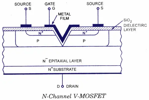
But these newer 2030+ are a different beast and as others and myself included - have found out that the level of DRIVE required to turn the beasts on, rivaled that of the V-MOS designs - ok did you catch that? TRENCH MOSFET designs. The type of designs that the Gate channel is grooved into the die amidst the substrate and makes them more linear.
EKL or whomever didn't seem to didn't follow that success with their first batch of the MOSFET designs - so these seem to be from another supplier - I just can't verify the V in the V-MOS - but the operation of this device fits that profile.
With the above being said, you have to look at the ERF-2030+ as a derivative of this method. To what flavor and extent? Well, take a look at the amount of capacitance that must be used now to obtain any linear drive level.
The efforts we have to make to obtain any sort of working power output makes me think that the parts that the 2030+ is, is from another supplier else our problems would have been far less than they are now.
Before - your AN-2030 or EKL-2030 required only that your existing capacitance parts be used and didn't require much fiddling with the BIAS to make it work - in fact, your Bias levels REQUIREMENT were far less power. And so the voltage / current needs were switched - from high-current low voltage bias of a diode threshold level - your P-N junction of a BI-POLAR onto now, a floating ON- voltage that was and is just below the Gate's Turn on voltage. We went from a high-current-low impedance path onto a high-impedance-low-current path which translates into a voltage requirement more than a current regulated at a specific voltage threshold.
What does this translate to? Higher levels of capacitance to the input admittance - or since were looking at the voltage components more than the current ones - you don't want your V-MOS design running - fluttering in a Class C mode like you'd get from non-biased designs of older Bi-polars - so you applied a higher voltage to the Gate - fantastic! But you forgot to adjust the input power to the bias ratios too.
Ratios? Yes, the Gate needs a voltage to turn on, and if you are running certain types of MOS designs, they require a Directional voltage - one that can give the Gate region (your V) enough field strength to turn on and REMAIN on - to make the substrate flow from Source To Drain (Or Drain to Source). So you don't reverse-bias the gate region else the field can collapse and you then run into a threshold issue again.
So to better define this...
You're trying to use an RF field at the same time you're using a Gate Bias DC voltage to force the part to turn on, and now you want it to follow the RF wave present in this same realm, the RF imposed over the DC state - which would be ok until the VECTOR of the RF wave places the inception power of that moment in time - below the threshold on stage - which will skew, if not clip - the output waveform - there lies the problem. Certain designs didn't like the vector of RF or any power - below that of a given on-level - and with high current switching power flowing underneath - this may seem a moot point but the effort they maker placed in making the trench-design work as well as it does - brings you to this brink
In the Bi-polar era - we saw things pretty plainly as Class A, AB or Class C - with D and others arriving as a methodology of application of power not just to the Base - but to all the parts of the transistor involved.
We don't get that luxury in the MOSFET realm. It is now done internally and we have to design around that. The Biasing we could do before as current - is now highly interactive within the part itself so we have to obtain and utilize windows or dynamic level ranges of signal that can be applied and yet operate the device linearly as possible.
Not necessarily by using excessive gate capacitance. But to use enough capacitance and power level range of signal (your dynamic element) to affect just the interaction of the Gates DC source bias and the RF power - becoming more of a VECTOR problem - not V-channel design per-se - but a directional or Vectoring of how to allow RF to be shaped in the output (from full peak to full trough) and keep it linear and yet forward amplification without cutoff .
Remember, before MOSFET we did all this with a diode and told the Bipolar to "stay on" only if RF was present and we got away with some cutoff by refueling the absent portions of the wave with a capacitive event we called Miller-effect.
So we just add a little less resistive element to the divider circuit to allow for more power in to the Gate line, and a slightly less resistive element to remove power from the line. Sounds simple enough right? Well, you'll need that and a bit of luck or a good Scope to help you see this vectoring problem.
But-it can be done. Only it becomes tricky when you have high levels of capacitance - it takes time to apply and remove the charges so you have to tailor the divider to obtain a given result.
So you have been warned.
Your divider will still need high-impedance sourcing and drainage - so that approach, we are ok with. But the ratios needed are highly part design specific as in - one type or configuration can work well for one type of Gate design, but not for all - so you will have to tailor the parts used in this event to make the show work.
So again, you make your divider a high-impedance type - but you may find yourself swapping and interchanging parts more on some MOSFETS' than other types of MOSFETs'. Yes, this is normal (AHEMN) yes, normal - because you have to adjust for a guesswork that the maker of the MOS device will not divulges all the details for you to follow - there simply isn't any - you have to make and take the time to apply the design you have to make it work for the Gate structure involved.
Stay tuned to this for I will be adding more of my notes to this as I go - right now I have some chores and animal husbandry to perform...
So I'm back now, and since I was trying to get this point across - I'm going to leave this here for you...

This is what I use as a GUIDE to help me find the best results from the layout of parts the conversion has left me to work with.
So if you have a 5K trimmer - great! If not, get some - you'll need them along with a 3.9K resistor of fixed value too. Diodes? 1N4148 can do well, follow your figures. But if you try the REGULATED approach, get some 5.6V 1-watt rated types. You can go higher in the Zener voltage but you might want to keep it simple and stay small with the 5.6 volts for now.
Why? Well, the 5.6 volt rating can be applied as a 1/2 value of expected input rated voltage.7.5 volts is about the highest you want to go in ability to rectify as well as provide protection.
Gates of most MOSFET's you can fit in there are rated inputs of about 20 volts Positive or Negative - peak. So with 5.6 volts, you're close to about 12 volts on same side of the diodes direction - so when it rectifies, do remember to add in the RF potentials in Voltage peaks too.
You can also find more research in this thread MOSFET conversions for upD858 and MB8719 boards - although it pops up on my post, don't forget to review the entire thread - lost of pages - there is invaluable resources embedded within the thread from many great participants and techs - some of the best in the business really - so best to take a moment and look into that thread too
Not just saying it as a metaphor, but in actuality - it fits the facts...
You have to remember the original design the AN-2030 - came from older days of needing an Automotive Spark Plug "trigger" that had nearly 0 ohmic drop with hardly any inductive effects of Ringing - since you were already using a highly inductive coil on top of the spark plug.
Don't believe me - go locate some older ECM from some vehicles in a junk yard dated about 1995 to 2005 - they too used AN types - why AN prefix, because they were commonly used around Little fuse and their umbrella of companies...for automotive purposes.
Anything from relay latching onto the spark plug and pulse width modulation for lamps and lighting and any type of sensor networks. Littlefuse and AN worked hand in hand and that's not bad...
But these newer 2030+ are a different beast and as others and myself included - have found out that the level of DRIVE required to turn the beasts on, rivaled that of the V-MOS designs - ok did you catch that? TRENCH MOSFET designs. The type of designs that the Gate channel is grooved into the die amidst the substrate and makes them more linear.
EKL or whomever didn't seem to didn't follow that success with their first batch of the MOSFET designs - so these seem to be from another supplier - I just can't verify the V in the V-MOS - but the operation of this device fits that profile.
In the power or V-MOSFETs the channel length is determined by the diffusion process, while in other MOSFETs the channel length depends upon the dimensions of the photographic masks employed in the diffusion process. By controlling the doping density and the diffusion time, much shorter channels can be produced than are possible with mask control of channel length. These shorter channels allow much more current densities which again contribute to larger power dissipations. The shorter channel length also allows a larger transconductance gm to be attained in the V-FET and very considerably improves the frequency response and the device switching time.
Excerpts from:
http://www.circuitstoday.com/v-fet-or-power-mosfets
With the above being said, you have to look at the ERF-2030+ as a derivative of this method. To what flavor and extent? Well, take a look at the amount of capacitance that must be used now to obtain any linear drive level.
The efforts we have to make to obtain any sort of working power output makes me think that the parts that the 2030+ is, is from another supplier else our problems would have been far less than they are now.
Before - your AN-2030 or EKL-2030 required only that your existing capacitance parts be used and didn't require much fiddling with the BIAS to make it work - in fact, your Bias levels REQUIREMENT were far less power. And so the voltage / current needs were switched - from high-current low voltage bias of a diode threshold level - your P-N junction of a BI-POLAR onto now, a floating ON- voltage that was and is just below the Gate's Turn on voltage. We went from a high-current-low impedance path onto a high-impedance-low-current path which translates into a voltage requirement more than a current regulated at a specific voltage threshold.
What does this translate to? Higher levels of capacitance to the input admittance - or since were looking at the voltage components more than the current ones - you don't want your V-MOS design running - fluttering in a Class C mode like you'd get from non-biased designs of older Bi-polars - so you applied a higher voltage to the Gate - fantastic! But you forgot to adjust the input power to the bias ratios too.
Ratios? Yes, the Gate needs a voltage to turn on, and if you are running certain types of MOS designs, they require a Directional voltage - one that can give the Gate region (your V) enough field strength to turn on and REMAIN on - to make the substrate flow from Source To Drain (Or Drain to Source). So you don't reverse-bias the gate region else the field can collapse and you then run into a threshold issue again.
So to better define this...
You're trying to use an RF field at the same time you're using a Gate Bias DC voltage to force the part to turn on, and now you want it to follow the RF wave present in this same realm, the RF imposed over the DC state - which would be ok until the VECTOR of the RF wave places the inception power of that moment in time - below the threshold on stage - which will skew, if not clip - the output waveform - there lies the problem. Certain designs didn't like the vector of RF or any power - below that of a given on-level - and with high current switching power flowing underneath - this may seem a moot point but the effort they maker placed in making the trench-design work as well as it does - brings you to this brink
In the Bi-polar era - we saw things pretty plainly as Class A, AB or Class C - with D and others arriving as a methodology of application of power not just to the Base - but to all the parts of the transistor involved.
We don't get that luxury in the MOSFET realm. It is now done internally and we have to design around that. The Biasing we could do before as current - is now highly interactive within the part itself so we have to obtain and utilize windows or dynamic level ranges of signal that can be applied and yet operate the device linearly as possible.
Not necessarily by using excessive gate capacitance. But to use enough capacitance and power level range of signal (your dynamic element) to affect just the interaction of the Gates DC source bias and the RF power - becoming more of a VECTOR problem - not V-channel design per-se - but a directional or Vectoring of how to allow RF to be shaped in the output (from full peak to full trough) and keep it linear and yet forward amplification without cutoff .
Remember, before MOSFET we did all this with a diode and told the Bipolar to "stay on" only if RF was present and we got away with some cutoff by refueling the absent portions of the wave with a capacitive event we called Miller-effect.
- In the realm of the Gate - you can't - you have to push enough voltage to keep the part just off - only Turn-on when RF is present - but also to remember the RF vectoring will add and subtract power from this threshold voltage to a larger degree due to the high-impedance state of voltage - no current flow.
- This is more of a DYNAMIC range issue - too much power applied can result in this effect. So to keep power lower and within limits allows us to keep DC bias issues from becoming an absence of power to maintain the Gates' on condition. (Lower AVG power levels beyond recovery times)
So we just add a little less resistive element to the divider circuit to allow for more power in to the Gate line, and a slightly less resistive element to remove power from the line. Sounds simple enough right? Well, you'll need that and a bit of luck or a good Scope to help you see this vectoring problem.
But-it can be done. Only it becomes tricky when you have high levels of capacitance - it takes time to apply and remove the charges so you have to tailor the divider to obtain a given result.
So you have been warned.
Your divider will still need high-impedance sourcing and drainage - so that approach, we are ok with. But the ratios needed are highly part design specific as in - one type or configuration can work well for one type of Gate design, but not for all - so you will have to tailor the parts used in this event to make the show work.
So again, you make your divider a high-impedance type - but you may find yourself swapping and interchanging parts more on some MOSFETS' than other types of MOSFETs'. Yes, this is normal (AHEMN) yes, normal - because you have to adjust for a guesswork that the maker of the MOS device will not divulges all the details for you to follow - there simply isn't any - you have to make and take the time to apply the design you have to make it work for the Gate structure involved.
Stay tuned to this for I will be adding more of my notes to this as I go - right now I have some chores and animal husbandry to perform...
So I'm back now, and since I was trying to get this point across - I'm going to leave this here for you...
This is what I use as a GUIDE to help me find the best results from the layout of parts the conversion has left me to work with.
So if you have a 5K trimmer - great! If not, get some - you'll need them along with a 3.9K resistor of fixed value too. Diodes? 1N4148 can do well, follow your figures. But if you try the REGULATED approach, get some 5.6V 1-watt rated types. You can go higher in the Zener voltage but you might want to keep it simple and stay small with the 5.6 volts for now.
Why? Well, the 5.6 volt rating can be applied as a 1/2 value of expected input rated voltage.7.5 volts is about the highest you want to go in ability to rectify as well as provide protection.
Gates of most MOSFET's you can fit in there are rated inputs of about 20 volts Positive or Negative - peak. So with 5.6 volts, you're close to about 12 volts on same side of the diodes direction - so when it rectifies, do remember to add in the RF potentials in Voltage peaks too.
You can also find more research in this thread MOSFET conversions for upD858 and MB8719 boards - although it pops up on my post, don't forget to review the entire thread - lost of pages - there is invaluable resources embedded within the thread from many great participants and techs - some of the best in the business really - so best to take a moment and look into that thread too
Last edited:
This being an old thread I can say we conclude that there aren't many success stories of the 2030+ in this thread. Now with that said, in another thread it was said that they in fact had achieved good results by simply subbing them in place and without other component changes. Now I'm left with the thoughts that I may have just gotten a bad batch along with other folks and that the successful installations are equivalent to a fishing story
I'm stuck with a bag of them....
Snake oil........
I'm stuck with a bag of them....
Snake oil........
I recently put 2 of the new and improved ERF2030'S in magnum S3. They work fine and I am getting good output.
Well, in the above post I did, you just may need to INCREASE the capacitance to the Gate...
Magnum uses this ..ERF2030'S BUT WITH very large CAPACITANCE...

.
If you remember in their RFX amp days...they used similar values to pump AND overcome their internal capacitance that would be working in series - which in CAPACITORS - brings the values to half their values (if equal - even less if not - lesser than the smaller of the two)
So you need to up some values guys...
in my post above, I was discussing the changes in the structure - so you just need to try larger capacitance to attain those power levels...
Gate Bias too - make it "stronger" (Current needs to flow thru in a larger quantity) to handle the voltage variations that occur while the Gate conducts - so the "Wash effect" needs more current and Voltage - so the Current needs to remain steady as well as voltage to overcome the Gates ability to filter and absorb it.
Magnum uses this ..ERF2030'S BUT WITH very large CAPACITANCE...
.
If you remember in their RFX amp days...they used similar values to pump AND overcome their internal capacitance that would be working in series - which in CAPACITORS - brings the values to half their values (if equal - even less if not - lesser than the smaller of the two)
So you need to up some values guys...
in my post above, I was discussing the changes in the structure - so you just need to try larger capacitance to attain those power levels...
Gate Bias too - make it "stronger" (Current needs to flow thru in a larger quantity) to handle the voltage variations that occur while the Gate conducts - so the "Wash effect" needs more current and Voltage - so the Current needs to remain steady as well as voltage to overcome the Gates ability to filter and absorb it.
If you also look carefully at the Magnum schematic, they've been working on the concepts of the Class Of Operation changes - so as you see they use the EN369 devices - ALONG WITH a switched in BIAS that occurs in SSB modes - TO ADD a Gate Threshold value to improve the SSB drive linearity.(TR53 and VR10)
While people think this is fun, the 13N10's, IRF520's and the OEM ERF2030's are all being mercilessly sacrificed at the sake of power - for the ERF is not available - what is one to use? Well, the 13N10 and the IRF - but the 13N10 win out due to power drive levels - they just look better - doesn't mean that the really are better, just they look better...
On a more serious note...
This Thread on the AT-6666 BIAS when you have no way to check many simply try to set the voltage and let it go at that - and hope the Scope don't lie (too much) about the Drivers' RF High-Sugar and Caloric output making the Finals power curve look too fat (Phat?)
But if you use only that method, then you run the risk of putting the Patient back on the Oeprating table (Hoo-boy!)...
While people think this is fun, the 13N10's, IRF520's and the OEM ERF2030's are all being mercilessly sacrificed at the sake of power - for the ERF is not available - what is one to use? Well, the 13N10 and the IRF - but the 13N10 win out due to power drive levels - they just look better - doesn't mean that the really are better, just they look better...
Max Headroom anyone?

Nice Specs!
Nice Specs!
On a more serious note...
This Thread on the AT-6666 BIAS when you have no way to check many simply try to set the voltage and let it go at that - and hope the Scope don't lie (too much) about the Drivers' RF High-Sugar and Caloric output making the Finals power curve look too fat (Phat?)
But if you use only that method, then you run the risk of putting the Patient back on the Oeprating table (Hoo-boy!)...
Paging @kopcicle - Attention Kopcicle, Report to Surgury STAT!
In that thread is another link to a LONGER and LARGER thread that many should read as this chronologically shows how this ERF/EKL mess evolved...If you also look carefully at the Magnum schematic, they've been working on the concepts of the Class Of Operation changes - so as you see they use the EN369 devices - ALONG WITH a switched in BIAS that occurs in SSB modes - TO ADD a Gate Threshold value to improve the SSB drive linearity.(TR53 and VR10)
While people think this is fun, the 13N10's, IRF520's and the OEM ERF2030's are all being mercilessly sacrificed at the sake of power - for the ERF is not available - what is one to use? Well, the 13N10 and the IRF - but the 13N10 win out due to power drive levels - they just look better - doesn't mean that the really are better, just they look better...
On a more serious note...
This Thread on the AT-6666 BIAS when you have no way to check many simply try to set the voltage and let it go at that - and hope the Scope don't lie (too much) about the Drivers' RF High-Sugar and Caloric output making the Finals power curve look too fat (Phat?)
But if you use only that method, then you run the risk of putting the Patient back on the Oeprating table (Hoo-boy!)...
Paging @kopcicle - Attention Kopcicle, Report to Surgury STAT!In that thread is another link to a LONGER and LARGER thread that many should read as this chronologically shows how this ERF/EKL mess evolved...
I'd rather launch squirrels into orbit than poke myself in the eye with yet another discussion about the ERF 2030 and it's ilk .
Search the forum or don't IDFC. it's there if you care to see it.
Mosfets for BJT's is a pennies for dollars solution for a problem that doesn't exist unless you're stealing money from the brain dead CB radio public.
Exit makes it work within strict limits. And don't get me wrong , it works. Ask Exit how it works, I really don't give an electrocuted and desiccated rat's ass. (picture available via a Siltronix 1011D)
12 volt RF is a dead issue unless you are Galaxy, Stryker, or whatever Uniden has become. Toshiba and Mitsubishi gave up on the 12v BJT decades ago and yet a devout few fools still hold on to some hope that Mosfets are their salvation ? Get real, wake up, read the data sheets in their stark black and white.
It's all your fault Andy . I might have been able to keep silent but you just had to stir the pot. Then again it might be because I released a perfectly good dual mosfet pos into the hands of a moron that didn't believe me and railed the PA into it's third meltdown because he read it would do 50 watts PEP and wouldn't leave well enough alone.
I think I'll watch baseball , without any fans in the stands, with my dog , who thinks I'm kinda special because I scratch his butt. Seems a better pastime than discussing an ERF2030 pos to death .
Hmmm...PERSONAL NOTE REMINDER: Gotta' get back to Starbucks for that "Turmeric" blend they offer...would you like cup?
Well, if blame has to be made, remember you're in two states of mind, if not three (BJT, Glass/IRON and FET) - we are just trying to keep up with you.
Don't need to lash out to anyone about something already spilled - I'm just trying to save people $$$ by NOT trying to overdo that which was overdone to begin with.
Biggest clue?
When they don't publish any Datasheet for the 2030 or it's predecessor so the results can be verified and duplicated by others. You want to blame someone - call Palomar and ask.
Funny how you reference when I'm learning right along with everyone else, that which you've known of for years. Ok, maybe not everyone - they have lives too...
So relax, we're in the same stadium, just different seats.
Keep your Mitt on, the guy on the Mounds' been known to throw wild.
They don’t publish a data sheet because then we’d all know exactly what rebadged component it actually is.
As long as they don’t provide a data sheet then I won’t be using them.
As long as they don’t provide a data sheet then I won’t be using them.
Sounds like everything produced by Palomar these days is crap and they are just trying to squeeze out as much money as they can from the American public before they close their doors forever as they feel like CB is dying and the company shall die with it because they are too dumb and lazy to broaden they're market to other fields of electronics.
Once and for all which company brand makes the best or at least real MOSFETs for rf applications ? The company's that supply other countries besides America with MOSFETs because you guys should know by now that only America gets all the garbage built to fail modern technology in all electronics that's sent here from over seas.
In all of Europe or wherever they don't have to worry about Palomar and fake components and disposable TV,s that fail in a week filling up the landfills and dumpsters allover the good ole USA.
In all of Europe or wherever they don't have to worry about Palomar and fake components and disposable TV,s that fail in a week filling up the landfills and dumpsters allover the good ole USA.
Hello to Andy and Varth Dader, been a while.
I've been advocating a move to 48 (50?) volts for a long time.
This allows a move to LDMos in similar packages ie; MRF101 or the slightly larger MRF300.
Hard to argue with 100w in the size of a bic lighter (less heatsink) and 300w in the TO-247 package.
Note: NXP regularly publishes data for 27.120 MHz (ISM) so most of your goesinta/goesouta work is already done.
If you want to go full silly and send it, I suggest a constant voltage welder and a sophisticated high current regulator.
The MRFX1K80H is only 15V more and just waiting for some enterprising soul to gang rape into a few large cabinets.
Lawerance Livermore already has, we're all just waiting to see what a few hundred of these 1,800-watt (class C) devices will do. (Something about defense department and alien technology I' sure) More importantly why would anyone want or need RF energy between 1.8 MHZ and 470 MHZ at 360,000 Watts?
All you have to do is embrace 50V and the one LDMos caveat, gates they be fragile.
I've found that building a driver stage limited in power so as to be incapable of overwhelming the gate is better than the fastest active attenuator.
Only other option is Class-E")
I've been advocating a move to 48 (50?) volts for a long time.
This allows a move to LDMos in similar packages ie; MRF101 or the slightly larger MRF300.
Hard to argue with 100w in the size of a bic lighter (less heatsink) and 300w in the TO-247 package.
Note: NXP regularly publishes data for 27.120 MHz (ISM) so most of your goesinta/goesouta work is already done.
If you want to go full silly and send it, I suggest a constant voltage welder and a sophisticated high current regulator.
The MRFX1K80H is only 15V more and just waiting for some enterprising soul to gang rape into a few large cabinets.
Lawerance Livermore already has, we're all just waiting to see what a few hundred of these 1,800-watt (class C) devices will do. (Something about defense department and alien technology I' sure) More importantly why would anyone want or need RF energy between 1.8 MHZ and 470 MHZ at 360,000 Watts?
All you have to do is embrace 50V and the one LDMos caveat, gates they be fragile.
I've found that building a driver stage limited in power so as to be incapable of overwhelming the gate is better than the fastest active attenuator.
Only other option is Class-E
Last edited:
dxChat
- No one is chatting at the moment.