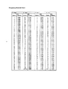
Petrusse Excalibur 2002
https://www.cbmuseum.nl/images/petrusse_escalibur_2002.jpg
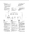
Mainboard is PTBM131A4X which is the same as for example Superstar 2000. Schematics at for example
http://www.cbtricks.com/radios/superstar/2000/graphics/superstar_2000_sch.jpg
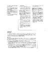
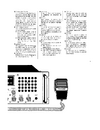
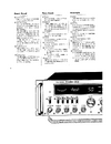
This radio has a FINE TUNE that only affects RX freq and a VFO knob (far right on the pic above) that affects both RX and TX freq. It does not show on the PTBM131A4X schematics above though and I have not been able to find the schematics for this particular radio so I am a little bit unsure where the VFO affects RX and TX frequencies. The knob has a middle "click" position so it is is quite easy to fix it in the center position.
I have aligned the PLL section and TX section and also done the RX alignment and all freq seems correct and RX receive is fine as well as power and modulation and low harmonics when looking at the scope.
My problem is that the TX freq is off approx +1.7kHz on all bands and all modes...

I have tracked it down to that when I go from RX to TX the mixing frequencies jumps up about 850 Hz and since both of the mixing frequencies does that the TX freq will go up by approx 1.7kHz.
Freq 27.205MHz in the measurements below (CH20):
When I am in USB mode and measure pin 1 on IC3 (oscillator input) I get 10.694979 MHz on both RX and TX which is well within specifications. If I switch to AM mode I get no reading in RX but in TX I get approx same freq as above in TX.
When I measure pin 4 on IC 3 (mixer input) I get a very fluctuating freq around 37.900MHz but if I move the measurement point to the intersection of C36 and C35 then I get 37.900109 in RX and 37.901772 in TX (AM mode). It also seems as the freq increases about 1Hz per 30 seconds in TX mode.
If I now move the freq measurement to TP1 which is pin 4 on IC2 the VCO mixer and its mixer input I get 20.105013 in RX and 20.105855 in TX, i.e. approx 840/850 Hz higher in TX than in RX.
Then I measure at TP2 which is pin 3 on IC2 and the buffered oscillator output: I see 17.795045 in RX and 17.795870 in TX. Again about 830/840 Hz higher in TX.
So in RX the output from pin 9 on IC 3 is showing correct freq: 37.900109 - 10.694979 = 27.20513 which is well within specs.
In TX the output from pin 9 on IC 3 is showing +1.7Khz off: 37.901772 - 10.694979 = 27.206793 and I see that also on my freq counter.
When I measure intersection R1/R2 at crystal X1 (10.240MHz) I get 10.239986 in RX mode and 10.240037 in TX mode in all modes and all bands. Difference is only 51Hz.
When I measure on pin 2 on IC1 (PLL02A) I get 2.310012 in RX and 2.310022 in TX. Difference is 10Hz.
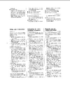
Seems to be caused by two sources since BOTH the VCO freq at pin 1 on IC 2 (VCO mixer but I measure at pin 3, TP 2) AND the local oscillator freq at pin 4 goes up approx 850Hz in TX mode.
What components in the VCO area as well as the areas around OSC 1(Q1), OSC2 (Q2), OSC 3 (Q10) and DC switches Q9 and Q3 could be going wrong ONLY in TX mode (since the drift happens only in TX mode)?
I am not suspecting any of the crystals since I have this +1.7kHz drift on ALL bands. I.e. I don't think that all crystals X2, X3, X4, X5 and X7 would be bad and that they would only be bad in TX mode?
I don't want to start removing components in this area until I understand what the root cause for this problem can be.
https://www.cbmuseum.nl/images/petrusse_escalibur_2002.jpg
Mainboard is PTBM131A4X which is the same as for example Superstar 2000. Schematics at for example
http://www.cbtricks.com/radios/superstar/2000/graphics/superstar_2000_sch.jpg
This radio has a FINE TUNE that only affects RX freq and a VFO knob (far right on the pic above) that affects both RX and TX freq. It does not show on the PTBM131A4X schematics above though and I have not been able to find the schematics for this particular radio so I am a little bit unsure where the VFO affects RX and TX frequencies. The knob has a middle "click" position so it is is quite easy to fix it in the center position.
I have aligned the PLL section and TX section and also done the RX alignment and all freq seems correct and RX receive is fine as well as power and modulation and low harmonics when looking at the scope.
My problem is that the TX freq is off approx +1.7kHz on all bands and all modes...
I have tracked it down to that when I go from RX to TX the mixing frequencies jumps up about 850 Hz and since both of the mixing frequencies does that the TX freq will go up by approx 1.7kHz.
Freq 27.205MHz in the measurements below (CH20):
When I am in USB mode and measure pin 1 on IC3 (oscillator input) I get 10.694979 MHz on both RX and TX which is well within specifications. If I switch to AM mode I get no reading in RX but in TX I get approx same freq as above in TX.
When I measure pin 4 on IC 3 (mixer input) I get a very fluctuating freq around 37.900MHz but if I move the measurement point to the intersection of C36 and C35 then I get 37.900109 in RX and 37.901772 in TX (AM mode). It also seems as the freq increases about 1Hz per 30 seconds in TX mode.
If I now move the freq measurement to TP1 which is pin 4 on IC2 the VCO mixer and its mixer input I get 20.105013 in RX and 20.105855 in TX, i.e. approx 840/850 Hz higher in TX than in RX.
Then I measure at TP2 which is pin 3 on IC2 and the buffered oscillator output: I see 17.795045 in RX and 17.795870 in TX. Again about 830/840 Hz higher in TX.
So in RX the output from pin 9 on IC 3 is showing correct freq: 37.900109 - 10.694979 = 27.20513 which is well within specs.
In TX the output from pin 9 on IC 3 is showing +1.7Khz off: 37.901772 - 10.694979 = 27.206793 and I see that also on my freq counter.
When I measure intersection R1/R2 at crystal X1 (10.240MHz) I get 10.239986 in RX mode and 10.240037 in TX mode in all modes and all bands. Difference is only 51Hz.
When I measure on pin 2 on IC1 (PLL02A) I get 2.310012 in RX and 2.310022 in TX. Difference is 10Hz.
Seems to be caused by two sources since BOTH the VCO freq at pin 1 on IC 2 (VCO mixer but I measure at pin 3, TP 2) AND the local oscillator freq at pin 4 goes up approx 850Hz in TX mode.
What components in the VCO area as well as the areas around OSC 1(Q1), OSC2 (Q2), OSC 3 (Q10) and DC switches Q9 and Q3 could be going wrong ONLY in TX mode (since the drift happens only in TX mode)?
I am not suspecting any of the crystals since I have this +1.7kHz drift on ALL bands. I.e. I don't think that all crystals X2, X3, X4, X5 and X7 would be bad and that they would only be bad in TX mode?
I don't want to start removing components in this area until I understand what the root cause for this problem can be.