
B
BOOTY MONSTER
Guest
ive got what i can on it done for the moment , just need a dry day and some help taking the homebrew 1/4wgp down and putting the new one up . gonna pull the ground radials off the 1/4 and use them on the 5/8 . and of course ill have to tune it after the grounds are on .
ill be using the ground wires and X off of this 1/4wgp on the 5/8 .

the ground radials/wires and the coax shield will attach to the bottom of the tuning ring on the single bolt .
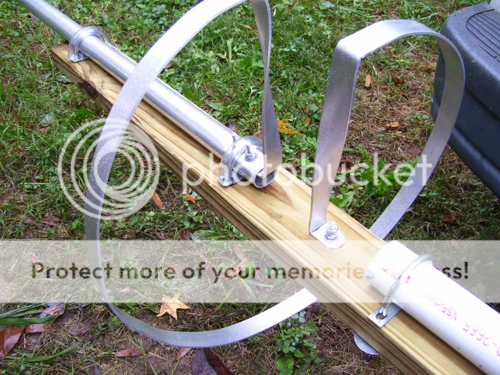
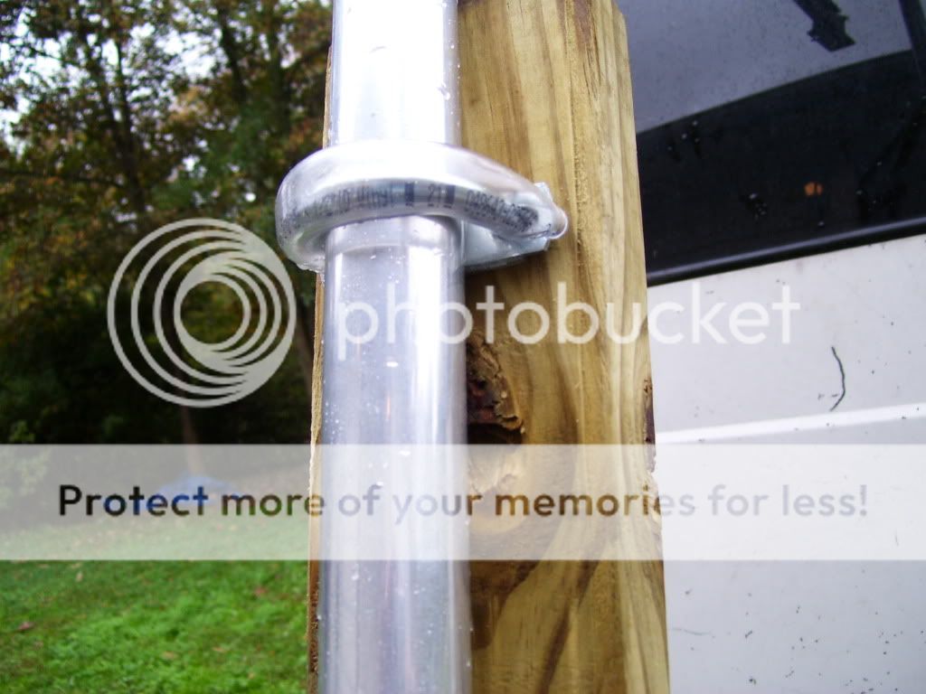
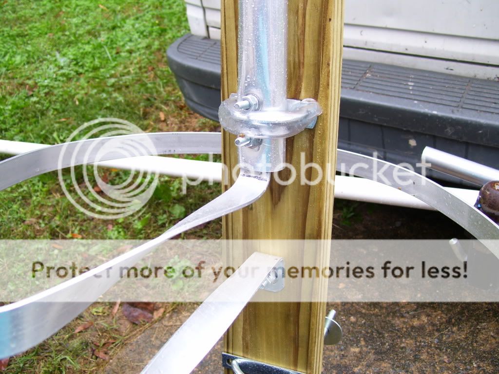
i used noalox on the tube sections and between the radiator and tuning ring behind the 2 bolts on the verticle . those 2 bolts give a super tight and very solid connection and the ends make a nice little saddle for the u clamp to rest in and keep the antenna from sliding down......just in case the pressure treaded 2x4 shrinks enough to allow that .
i also used some plastic tubing on the U clamps so they wouldnt be a radiating part of the antenna .
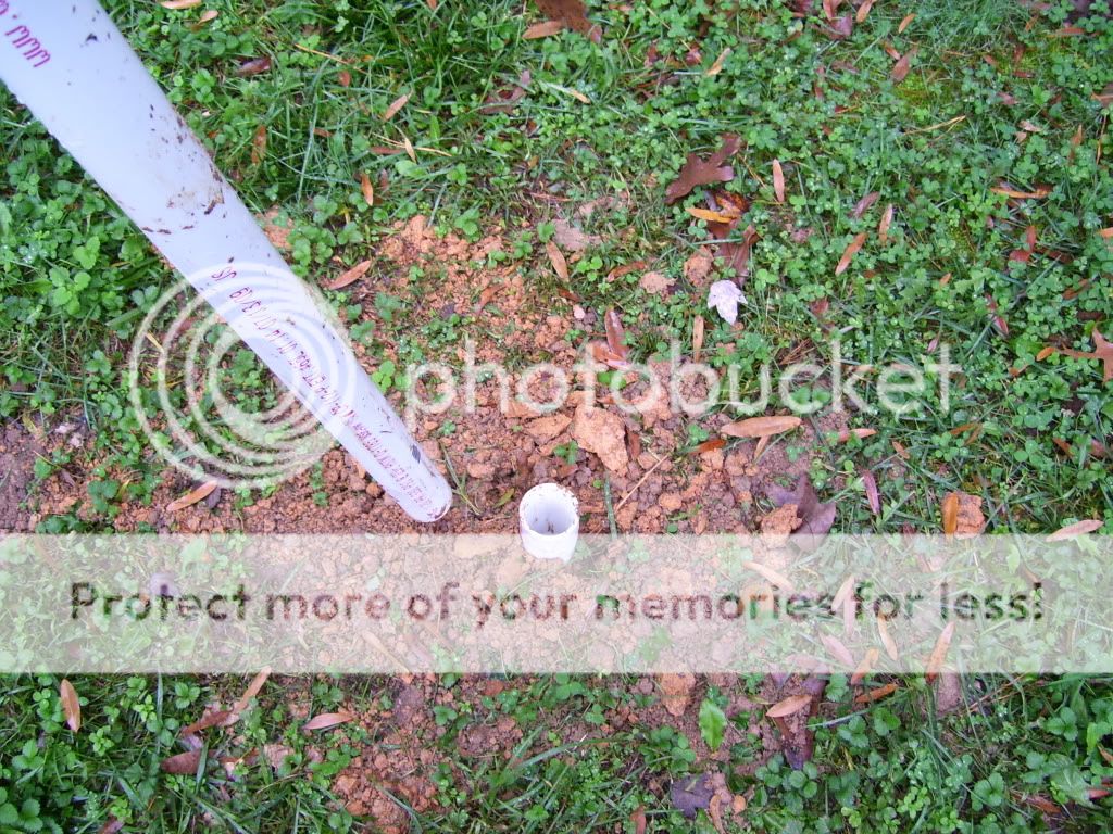
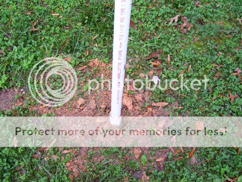
for a temporary tuning place i put a 2 foot 2 inch pve pipe in a hole and im using a 10 foot 1 1/2 inch peice of pvc for a mast . pull it out for adjusting vswr and stick it back in to see what it is .
the center coax conductor will be held in place on the tuning ring with a wooden clothes pin for checking and setting vswr and then a hole will be drilled in the ring at best tuning place and and a ring terminal and SS nut and 2 bolt with a lockwasher will secure it . every nut and bolt has a flat washer and a lock washer .
the verticle is 22 1/2 feet tall and theres 6 inches of over lap on each section . theres just a simple rubber cap on the top . i do expect the vswr to possibly rise a point or 2 from tuning the feedpoint 9 feet off the ground to 23-24 feet in the air , but if i can get to 1.2 or less on the ground that wont be a issue in the real world .
a few more pics ....
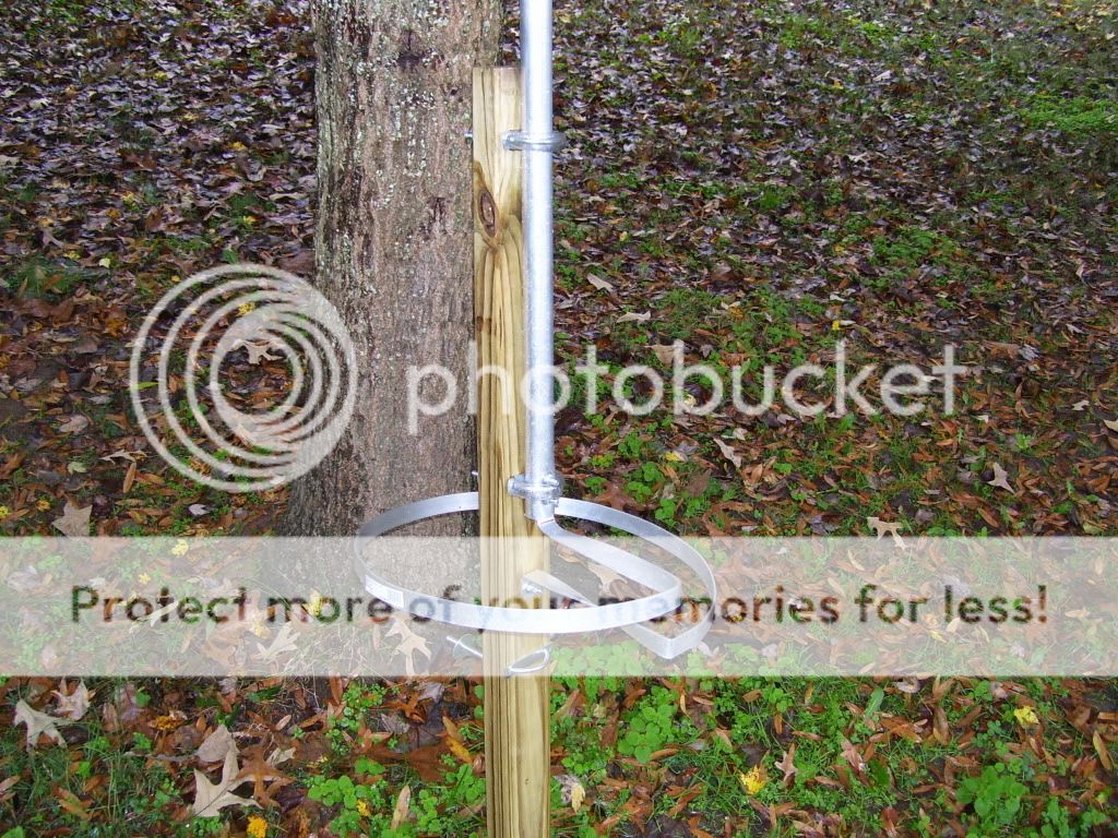
with the verticle not fully telescoped it about 8 - 8 1/2 feet tall .

seems like its taking me forever :Frustrated: but it is comming along :yes: .
i hope to have it up and talking in the next few days . ill post a few more pics with it in the air and the ground elements installed when its up .
if you see where ive made any mistakes let me know !! :Laugh:
ill be using the ground wires and X off of this 1/4wgp on the 5/8 .
the ground radials/wires and the coax shield will attach to the bottom of the tuning ring on the single bolt .
i used noalox on the tube sections and between the radiator and tuning ring behind the 2 bolts on the verticle . those 2 bolts give a super tight and very solid connection and the ends make a nice little saddle for the u clamp to rest in and keep the antenna from sliding down......just in case the pressure treaded 2x4 shrinks enough to allow that .
i also used some plastic tubing on the U clamps so they wouldnt be a radiating part of the antenna .
for a temporary tuning place i put a 2 foot 2 inch pve pipe in a hole and im using a 10 foot 1 1/2 inch peice of pvc for a mast . pull it out for adjusting vswr and stick it back in to see what it is .
the center coax conductor will be held in place on the tuning ring with a wooden clothes pin for checking and setting vswr and then a hole will be drilled in the ring at best tuning place and and a ring terminal and SS nut and 2 bolt with a lockwasher will secure it . every nut and bolt has a flat washer and a lock washer .
the verticle is 22 1/2 feet tall and theres 6 inches of over lap on each section . theres just a simple rubber cap on the top . i do expect the vswr to possibly rise a point or 2 from tuning the feedpoint 9 feet off the ground to 23-24 feet in the air , but if i can get to 1.2 or less on the ground that wont be a issue in the real world .
a few more pics ....
with the verticle not fully telescoped it about 8 - 8 1/2 feet tall .
seems like its taking me forever :Frustrated: but it is comming along :yes: .
i hope to have it up and talking in the next few days . ill post a few more pics with it in the air and the ground elements installed when its up .
if you see where ive made any mistakes let me know !! :Laugh:


