
So here's a project that languished on the back burner since April, more or less. The objective is to replace a bad high-voltage transformer in a Pride DX300 or KW-one. For decades, RF Parts had that one in stock, and for a fairly reasonable price. They ran out a few years back and chose not to pour money into having more of them made. Probably a wise business decision, that. You could hire a transformer shop to design and build one like the original. Would be a pricey proposition. Feel free.
But people will still burn up this component and want to replace it. We worked up a substitute a while back, and getting it to market as a DIY kit has been a low priority. That is until I acquired a totally-discombobulated DX300 to rebuild and eventually sell off. That amplifier becomes the photo model to produce fully detailed instructions for getting it installed and working. No point selling a technical product without detailed instructions.
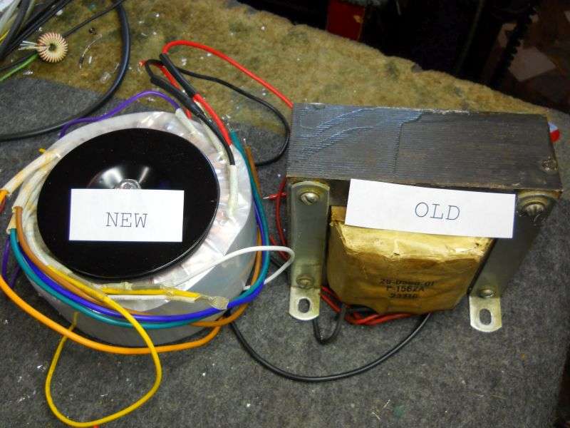
The new transformer is a toroid, and will just barely fit in place of the original part. It was built using what the industry calls an "economy" or "E-I" core. A single bobbin slides over the middle finger of the letter "E" shaped layers of iron. They are stacked with the "I" shaped pieces interleaved. The new transformer is a toroid, shaped like a big doughnut.
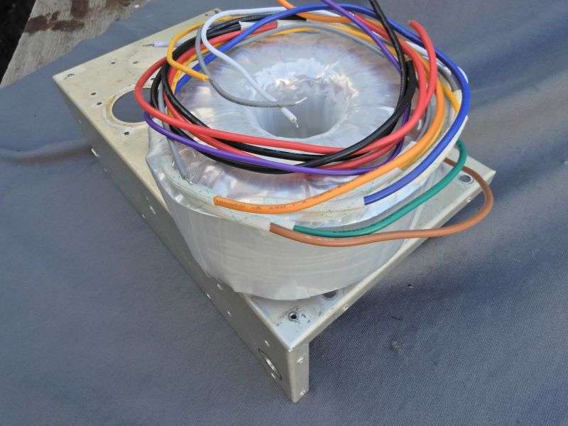
And yes, it just barely fits.
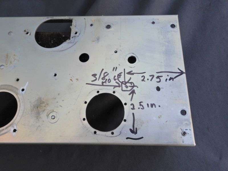
You do need to drill a hole for the mounting bolt.
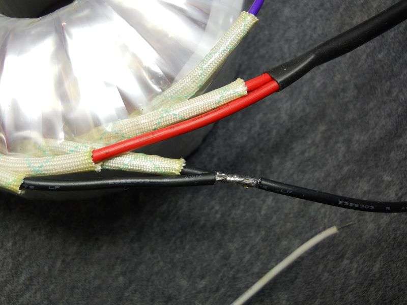
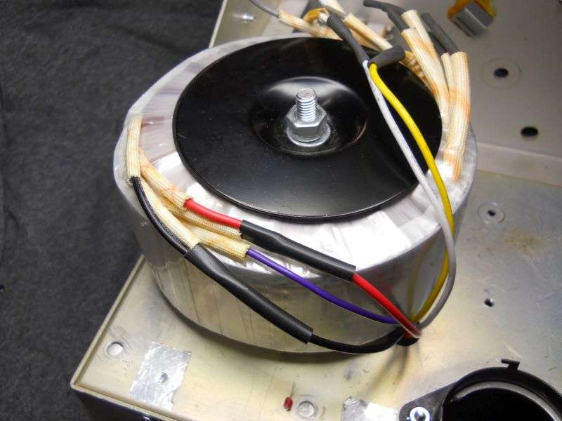
The new transformer is different in other ways. It has two 6-Volt windings we won't be using. That's four of the wires you see that just get cut off short. It has two 115-Volt primary windings, each with a red wire and a black wire. It's easier to just splice the two black wires together, and the two red wires close to the transformer. This way you only need to fish two primary wires into the deck and over to the tie strip underneath.
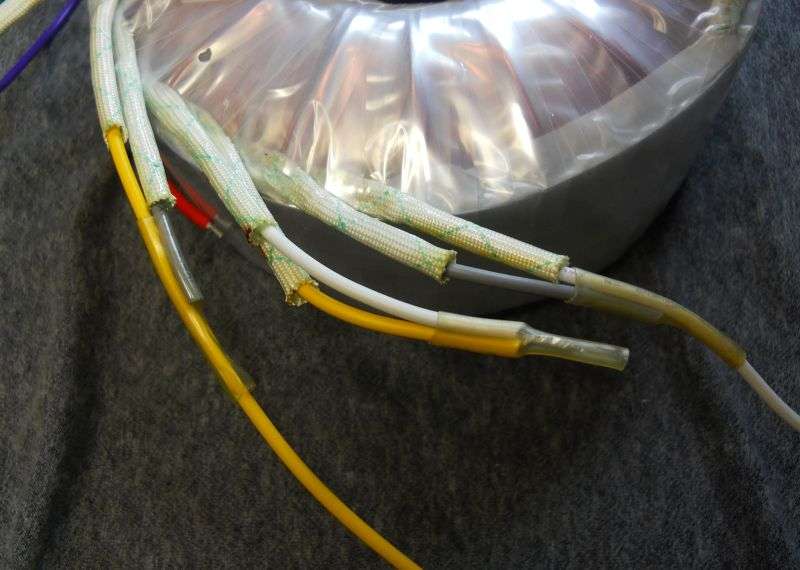
It's also different on the secondary side. It has two high voltage windings of 430 Volts each. One white and one yellow wire on each. We'll wire them in series for 860 Volts. This is still only half the original transformer's HV output. The gray wires are a lower-voltage tap we aren't using, so they're clipped off short and insulated.
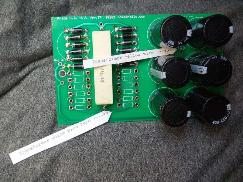
So wait, you say. What good is half the original transformer voltage? The high-voltage replacement circuit board we sell for the original transformer is reconfigured as a full-wave voltage doubler circuit, instead of the full-wave bridge circuit used with the factory transformer's 1700-Volt output. This requires only half the rectifier diodes used for the bridge circuit. But it does require filter caps with double the capacitance of the factory setup, 220uf in place of the factory-stock 100uf. Never mind why, this post will be stupidly long without that explanation. The enormous white power resistor is the surge limiter. Should make the power switch last longer, and limit damage if there is a short across the amplifier's HV circuit.
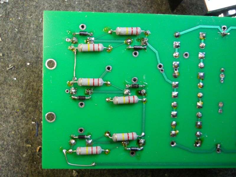
One more mod is done to this board, on the solder side. A reverse-polarity protection diode is installed across each of the six filter capacitors. An overload can put a surge of reverse polarity onto the filter capacitors. This can only occur in a doubler circuit. Doesn't seem to happen with bridge rectifiers. The six black diodes function the same as the reverse-protection diode in a mobile radio. It will act as a 'crowbar' and become a dead short only when the polarity is backwards. This protects the filter capacitor from reverse damage. The diode will be a one-time sacrificial protector, and fail as a dead short from the surge current. But 1N4007 diodes are a lot cheaper than filter caps, and they serve only as cheap insurance. So long as everything is working normally, those six diodes act as if they aren't even there to start with.
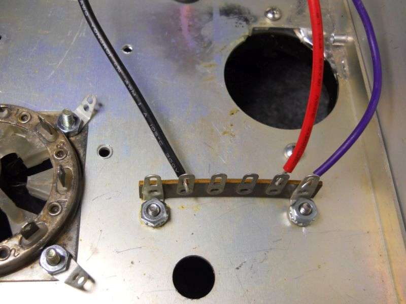
Five wires get stuffed through a hole in the deck. The violet wire is the transformer's internal shield. It just gets grounded.
The black and red wires go where the original HV transformer's two black wires were removed. This example is missing a lot of what's in a completed amplifier, but it gets the idea across.
This is the first draft of more detailed instructions we'll need to actually sell this setup. Gotta buy some more of this transformer first, and come up with a way to package a ten-pound transformer safely with the circuit board.
But hey, it's progress.
73
But people will still burn up this component and want to replace it. We worked up a substitute a while back, and getting it to market as a DIY kit has been a low priority. That is until I acquired a totally-discombobulated DX300 to rebuild and eventually sell off. That amplifier becomes the photo model to produce fully detailed instructions for getting it installed and working. No point selling a technical product without detailed instructions.
The new transformer is a toroid, and will just barely fit in place of the original part. It was built using what the industry calls an "economy" or "E-I" core. A single bobbin slides over the middle finger of the letter "E" shaped layers of iron. They are stacked with the "I" shaped pieces interleaved. The new transformer is a toroid, shaped like a big doughnut.
And yes, it just barely fits.
You do need to drill a hole for the mounting bolt.
The new transformer is different in other ways. It has two 6-Volt windings we won't be using. That's four of the wires you see that just get cut off short. It has two 115-Volt primary windings, each with a red wire and a black wire. It's easier to just splice the two black wires together, and the two red wires close to the transformer. This way you only need to fish two primary wires into the deck and over to the tie strip underneath.
It's also different on the secondary side. It has two high voltage windings of 430 Volts each. One white and one yellow wire on each. We'll wire them in series for 860 Volts. This is still only half the original transformer's HV output. The gray wires are a lower-voltage tap we aren't using, so they're clipped off short and insulated.
So wait, you say. What good is half the original transformer voltage? The high-voltage replacement circuit board we sell for the original transformer is reconfigured as a full-wave voltage doubler circuit, instead of the full-wave bridge circuit used with the factory transformer's 1700-Volt output. This requires only half the rectifier diodes used for the bridge circuit. But it does require filter caps with double the capacitance of the factory setup, 220uf in place of the factory-stock 100uf. Never mind why, this post will be stupidly long without that explanation. The enormous white power resistor is the surge limiter. Should make the power switch last longer, and limit damage if there is a short across the amplifier's HV circuit.
One more mod is done to this board, on the solder side. A reverse-polarity protection diode is installed across each of the six filter capacitors. An overload can put a surge of reverse polarity onto the filter capacitors. This can only occur in a doubler circuit. Doesn't seem to happen with bridge rectifiers. The six black diodes function the same as the reverse-protection diode in a mobile radio. It will act as a 'crowbar' and become a dead short only when the polarity is backwards. This protects the filter capacitor from reverse damage. The diode will be a one-time sacrificial protector, and fail as a dead short from the surge current. But 1N4007 diodes are a lot cheaper than filter caps, and they serve only as cheap insurance. So long as everything is working normally, those six diodes act as if they aren't even there to start with.
Five wires get stuffed through a hole in the deck. The violet wire is the transformer's internal shield. It just gets grounded.
The black and red wires go where the original HV transformer's two black wires were removed. This example is missing a lot of what's in a completed amplifier, but it gets the idea across.
This is the first draft of more detailed instructions we'll need to actually sell this setup. Gotta buy some more of this transformer first, and come up with a way to package a ten-pound transformer safely with the circuit board.
But hey, it's progress.
73
