I'll have a poke around with my DMM later after work.. Many thanks for your input! I've known about using transistors in this manner for a long time, I've used something similar in a few of my other projects (non radio-related) but for whatever reason it didn't even occur to me that the same would work here. This has been a productive discussion so far..

You are using an out of date browser. It may not display this or other websites correctly.
You should upgrade or use an alternative browser.
You should upgrade or use an alternative browser.
-
You can now help support WorldwideDX when you shop on Amazon at no additional cost to you! Simply follow this Shop on Amazon link first and a portion of any purchase is sent to WorldwideDX to help with site costs.
-
A Winner has been chosen for the 2026 July 4th Retevis RA89R Giveaway! Click Here to see who won!
Quick and Dirty Class "AB" mod for KL300p
- Thread starter eagle1911
- Start date
Ok, fresh pics of the progress so far.. Pretty much done except for the relay/transistor circuit to key the bias only when transmitting, but for folks wanting to perform this mod IMO it's optional. I plan to implement it in my amp, but the amp will work perfectly with the bias applied all the time while the amp is powered on. If you use this amp as a mobile and decide to just let the bias run all the time it's very important to remember to turn the amp off whenever you leave the vehicle, otherwise your battery could possibly be drained. I use mine as a QRP amp, so it's always connected to a power supply.
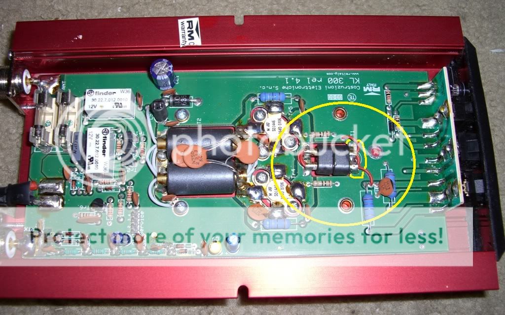
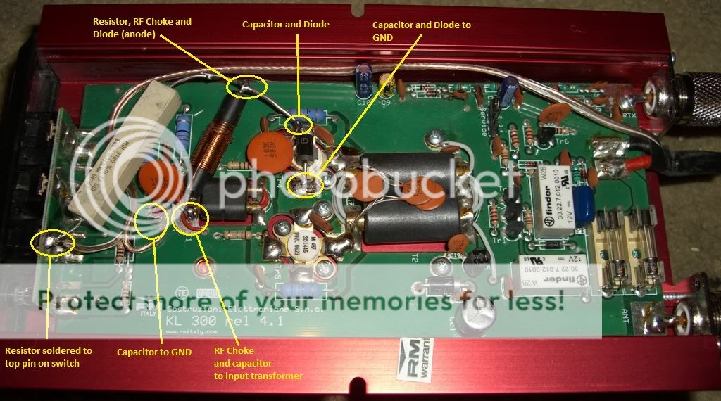
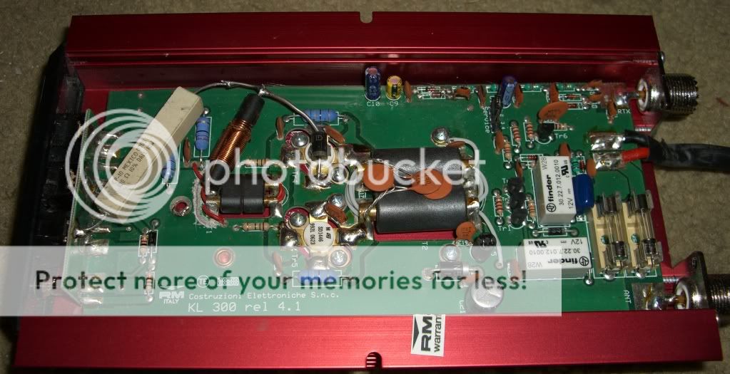
I've included descriptions in the photos with each connection and it's components. Below is also a pic of the amp before modification with the dremel cut marked and circled. Just don't cut through the wires that are in the transformer! They need to remain connected exactly as they are.
Special thanks to Shockwave for his valuable input.. and thanks to all who have replied. Some very good ideas have been presented in this thread.
Oh and total cost of this mod is less than $10 in Radio Shack parts and maybe an hour assembling.. The signal reports are great, the output looks clean on the scope. I don't have a spectrum analyzer so I can't speak for a reduction in Harmonics and IMD, but there should be a reduction in all types of distortion as long as the amp isn't being overdriven.
Last edited:
So, after more testing I found that a lower value resistor is needed in the bias circuit. Using the 100 ohm 10W resistor there was too much voltage sag on speech peaks, which causes the amp to run into class C territory. I decided that halving the resistance should do it, so I took out the 100 ohm, popped in a 50 ohm and took some voltage readings at the bases of the transistors: .650V under full load, .685 at idle. I also noticed a slight increase in power output, about 5% across the frequency range, and the transistors seemed to run just slightly hotter running into an MFJ dummy load. Everything still looks just fine on the scope. So far these are promising results..
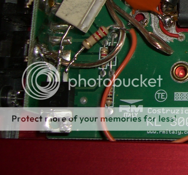
After replacing the resistor, the transistor switch that was described earlier went from optional to a necessity. The 50 ohm resistor heated up more than I wanted when the bias circuit was allowed to run all the time, so below you'll find a pic of the solution for that.
The transistor used is a TIP42G PNP power transistor. You don't necessarily need a power transistor, a small-signal PNP will do the job in most cases, but since this mod relies on thick component leads for structural support to avoid needing a PCB it seemed ideal. The resistor that the wire from the relay diode connects to is 220 ohms. The 220 ohm resistor is connected to the base pin (right in pic) of the TIP42G transistor. The transistor's emitter pin (leftmost in pic) is connected to the top pin on the front panel switch as in the picture. The last (middle) pin on the TIP42G is connected to the 50 ohm resistor in the bias circuit itself.
*It's VERY important to ensure that everything is positioned so that the tab on the TIP42G cannot touch ground, so avoiding anything metal is the best way to insure this..
the current your bias circuit needs to be able to supply to the transistor bases without sagging below about .6v to keep the amp in class AB depends on the beta of the transistors been biased and the current you draw in the collectors,
m beta sd1446's are pretty high gain devices @27mhz but your 100ohm dropping resistor is too high in value to keep the amp in class AB when you apply higher drive levels")
edit you beat me to it
m beta sd1446's are pretty high gain devices @27mhz but your 100ohm dropping resistor is too high in value to keep the amp in class AB when you apply higher drive levels
edit you beat me to it
Many thanks! I very much like this forum by the way.. there is a lot of really useful knowledge here.
As I was researching the idea of adding simple bias to improve the performance of cheap class C amps I found that while descriptions were plentiful, pictures were not so my intention here has been to provide a pictorial of my progress so that people with basic questions about bias might be able to get a better understanding of how to implement it. As I said in the OP there are much better bias circuits than the simple diode clamp circuit described in this thread. This modification therefore has it's limits as far as how much improvement can be seen, but some improvement is better than none IMO. The results are promising so far..
This project was born out of necessity really though.. I'm on a small hobby budget lately, so any ways that I can find to improve inexpensive equipment to bring the performance closer to that of more expensive gear are golden to me, not to mention the enjoyment I get from getting my hands-on DIY fix..
Just wanted to update this mod..
Upon consulting the Motorola EB63 bulletin (uses a very similar bias scheme as described here in this mod) I noticed that they incorporate a 500uF electrolytic capacitor to provide extra current during SSB peaks. This seemed like a great idea, so I've added it to my mod as well.
I also replaced the .01uF caps with smaller, lower voltage units that take up less space and reduced the 10W power resistor's value from 50ohms to 40ohms for more quiescent current through the transistors:
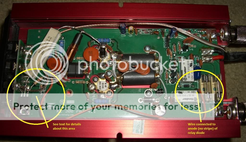
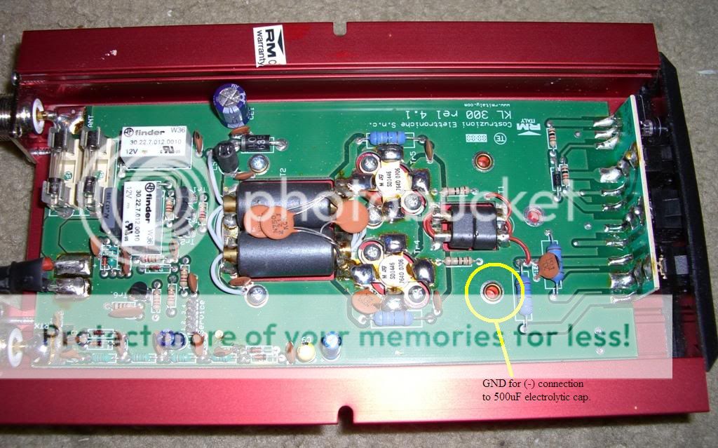
This is a pic of a similar amp without the mod. This is just to show where I connected the (-) lead of the cap.
This is the finished mod:
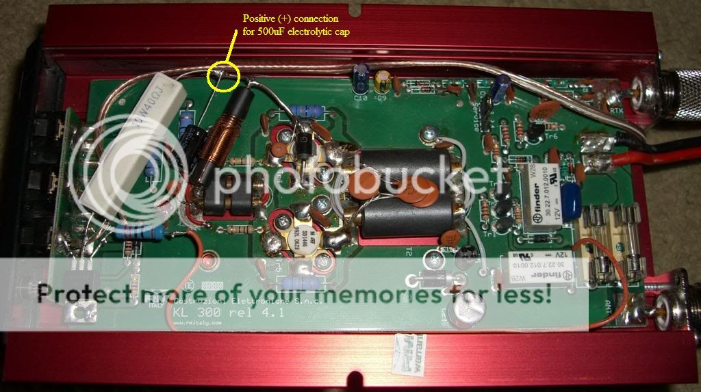
Upon consulting the Motorola EB63 bulletin (uses a very similar bias scheme as described here in this mod) I noticed that they incorporate a 500uF electrolytic capacitor to provide extra current during SSB peaks. This seemed like a great idea, so I've added it to my mod as well.
I also replaced the .01uF caps with smaller, lower voltage units that take up less space and reduced the 10W power resistor's value from 50ohms to 40ohms for more quiescent current through the transistors:
This is a pic of a similar amp without the mod. This is just to show where I connected the (-) lead of the cap.
This is the finished mod:
Last edited:
This is a "quick and dirty" class AB mod for the KL300p that I ran across some time ago. While this description is for the KL300p, this method of providing a small bias source can be applied to just about any class C amp. Basically any amp that grounds the bases of the transistors via an inductor is class C. In this case, the inductor is part of the input transformer.
Procedure: First I used a dremel tool to carve a notch all the way around the outside end (closest side to the switch assembly) of the input transformer, which is the smaller of the two transformers on the amp PCB. This disconnects the transformer from ground. Make very sure that you cut completely through the ground trace all the way around that end of the transformer. If you check for continuity with a DMM you'll get a reading of ~5 ohms. If you get a reading of 0 ohms, recheck to make sure that you've cut completely through the ground copper all the way around the end of the transformer.
I invented that mod back in 2004 and posted it on Plowboys mods, as I believe in 2008 or 2009!
GOOD WORK!!
I used a large 10W 100ohm resistor in line as well, one end of which I connected to the "Pre + Lin" side of the power switch which is on the topmost pin. When the switch is on, this pin is a source of 13.8V. This way, the bias is only supplied if the amp is on. This resistor limits the current that is supplied to the transistors, and it is connected in series with a large 3A silicon diode (1N5402), the side of which is physically touching the top of one of the SD1446s (there is thermal paste between the two) and the cathode end (stripe) is connected to ground right at the transistor on one of the emitter tabs. As you may already know a diode is simply a PN junction, and so this diode limits the bias voltage to the forward voltage drop of a silicon PN junction, generally .6-.7V depending on the junction temperature. At the connection point between the 10W resistor and the diode, I soldered one end of an RF choke (available from Radio Shack) which ensures RF cannot pass as we only want DC. The other end is connected to the brass tubes in the input transformer, on the same side as the cut that was made with the dremel. This replaces the ground connection that was there with the bias voltage. This completes the rudimentary bias supply. This small voltage applied to the bases (.6-.7V) is just right to keep the transistors turned "on" at all times, which means your amp is now class AB. Since the components used are fairly heavy-duty, the thick leads make for a nice stable structure so you don't have to worry about things moving around much.
This is a quick and dirty mod, partly due to limited room, and partly due to my feelings that simplicity is best for such an inexpensive amp.. however I see this same basic supply frequently in many 10-11m amps and even some Mirage VHF amps that are classified AB so by performing it you're getting very similar results to many major name manufacturer's amps and most other simple class AB amps.. In fact, since there is temperature tracking due to the physical arrangement of the diode and transistor you're actually a step ahead of many manufacturers.
There are much more complex bias designs out there that are meant to make sure the transistors are biased within precise parameters under all types of condition .. so if you really wanted to you could go much further with it and get even better results. This simple mod, combined with an effort to avoid overdriving the amp can help ensure that there is a reduction in the amount of distortion produced. If you think you're getting "crunchy" audio or fuzzy output then this mod might be just the thing you need.
Here's a pic of the end result:
Anyway, I just thought folks here might like to have a good description and pic of this mod, since I know that many people are confused by bias and amp classes in general and how they are applied in real-world hardware.. this might help remove some of the confusion. Plus, if there are people out there with KL300p's that want cleaner SSB output and less distortion this will likely help them out too..
GOOD JOB!! Employing the RF filtering!

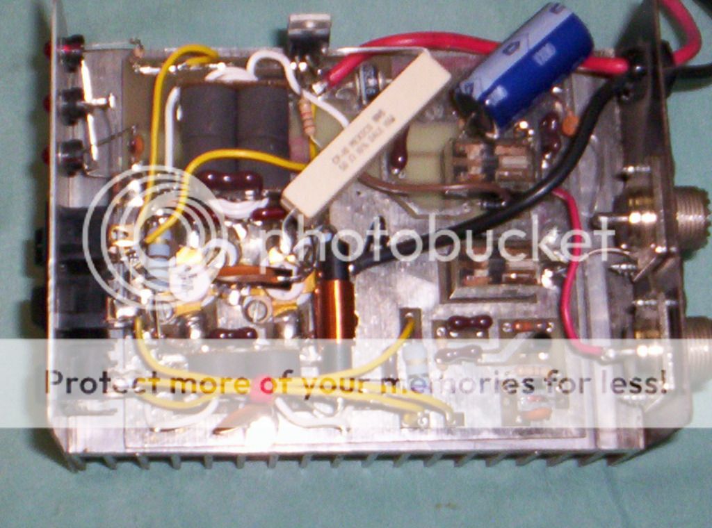
Great stuff here! I decided to do this mod on a little Silver Eagle 200 I got for working on a guys radio last week. It's a 2 X MRF455 class C box with no SSB delay. Since Eagle1911 has the rights to the "Quick and Dirty class AB Mod" I'll call mine the "White 'n' Nerdy class AB Mod"! Attached is a pic.
Once i got it all done, it works awesome, looks great on my O'scope, nice clean output. Does about 100W on low output, about 150W on high output, PEP. I did use a different resistor to the TIP42G transistor, as 220 ohms was keeping it "turned on", letting voltage go thru it at all times. I found that 1k ohms works perfect for switching the voltage.
Since this box did not have any SSB delay, I installed a 2200uF 35V capacitor across the relay coil. That gives me a nice delay for SSB, but isn't too long to interfere with AM should I want to use it for that mode.
Great thread, thanks to all that posted info and especially to Eagle1911 for the continued progress of the project!
~Cheers~
Nice, do you have some heat sink compound between your tracking diode and the pill surface? if not you'll get better thermal contact with some.Great stuff here! I decided to do this mod on a little Silver Eagle 200 I got for working on a guys radio last week. It's a 2 X MRF455 class C box with no SSB delay. Since Eagle1911 has the rights to the "Quick and Dirty class AB Mod" I'll call mine the "White 'n' Nerdy class AB Mod"! Attached is a pic.
Once i got it all done, it works awesome, looks great on my O'scope, nice clean output. Does about 100W on low output, about 150W on high output, PEP. I did use a different resistor to the TIP42G transistor, as 220 ohms was keeping it "turned on", letting voltage go thru it at all times. I found that 1k ohms works perfect for switching the voltage.
Since this box did not have any SSB delay, I installed a 2200uF 35V capacitor across the relay coil. That gives me a nice delay for SSB, but isn't too long to interfere with AM should I want to use it for that mode.
Great thread, thanks to all that posted info and especially to Eagle1911 for the continued progress of the project!
~Cheers~
Maybe try filing a flat spot on one side of the diode also.
Hiya Mack!
Yes, I do have plenty of heatsink compound on the diode, I made sure there was plenty on the contacting surfaces of both the diode and the MRF455. Good to go there. The picture doesn't show it much because of how the pic was snapped, stuff in the way.
(edit) Poor picture quality too, I might add...
~Cheers~
dxChat
- No one is chatting at the moment.
