I am new to this site, searching on google has led me to this place. I have a friend who is having me look at his rci2980. It has voltage to the regulator on the board, 15 volts to the two outer pins and 7 at the center. The problem is that none of the face of the radio lights up, no freq counter, channel display, tx/rx... I suspect the issue to be the power supply board eptossb62a. R702 is completely fried beyond recognition of the value. With that being said, I have searched all over the net for a schematic that shows the value of r702 to no avail. I have found several schematics of the eptossb62a, but in all of them r702 is not used, just a spot on the board marked with no resistor shown in that location. My question is this; does anyone on here know the value of r702 or would be willing to pop the top off their 2980 to find out for me? Any help would be greatly appreciated. Thanks -Alex


You are using an out of date browser. It may not display this or other websites correctly.
You should upgrade or use an alternative browser.
You should upgrade or use an alternative browser.
-
You can now help support WorldwideDX when you shop on Amazon at no additional cost to you! Simply follow this Shop on Amazon link first and a portion of any purchase is sent to WorldwideDX to help with site costs.
-
A Winner has been chosen for the 2026 July 4th Retevis RA89R Giveaway! Click Here to see who won!
Ranger rci2980 power supply question.
- Thread starter Alex Faught
- Start date
Check the voltage from the transformer to the regulator board first. It should be around ~18v. If it is OK; then the regulator is probably fried. I would also replace the two caps closest to that fried resistor (replace that too), as heat will damage them. Didn't look at the schematic to that radio, but if there is a zener on that board, I'd also replace that as well.
Just some first-blush thoughts on what I would do . . .
The rest of that radio chassis - IIRC - is the same thing as a Galaxy DX99. Been awhile since I last worked on one.
Just some first-blush thoughts on what I would do . . .
The rest of that radio chassis - IIRC - is the same thing as a Galaxy DX99. Been awhile since I last worked on one.
Check the voltage from the transformer to the regulator board first. It should be around ~18v. If it is OK; then the regulator is probably fried. I would also replace the two caps closest to that fried resistor (replace that too), as heat will damage them. Didn't look at the schematic to that radio, but if there is a zener on that board, I'd also replace that as well.
Just some first-blush thoughts on what I would do . . .
The rest of that radio chassis - IIRC - is the same thing as a Galaxy DX99. Been awhile since I last worked on one.
I have looked around on the internet looking for a schematic. Every one I have come across shows that spot on the board as not being used. I was hoping someone on here might have one that the could pop the cover off of and post it's value.
Ask for 'Chip' @ the 'Radio Shop Supply' in S.Ca. They work on Rangers, Galaxy, and RCI radios. He can tell you . . .
http://www.radioshopsupply.com/
http://www.radioshopsupply.com/
RCI 2980 uses the same EPT0SSB62A supply board as the Galaxy DX11B and DX22B. R702 is a 47ohm/ 1watt. I would replace it with a 47ohm/ 2watt.

hope this helps. 73s.
- 399
hope this helps. 73s.
- 399
Last edited:
Hello guys, I just new to this so guys go easy on me here lol, my question is, I just bought myself RCI 2980 I bought it in the USA but I am from the UK I do know USA is 120v and the UK is 220v I have took off the covers of the radio the original ETP 8620129 transformer is in it and working very well with 120v, on the left-hand side of the transformer I do know the white wire is for 120v is the red wire for 220v if anyone can help me with this issue, with thanks, Willie...
Attachments
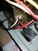
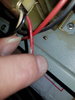

Hi Willie, welcome to WWDX. I would be surprised if any radios for the American market would have a provision for 220v. That being said, I do not know this radio at all. You might get more responses if you start a new thread, I am sure someone will come along that has the answer for you.Hello guys, I just new to this so guys go easy on me here lol, my question is, I just bought myself RCI 2980 I bought it in the USA but I am from the UK I do know USA is 120v and the UK is 220v I have took off the covers of the radio the original ETP 8620129 transformer is in it and working very well with 120v, on the left-hand side of the transformer I do know the white wire is for 120v is the red wire for 220v if anyone can help me with this issue, with thanks, Willie...
Chris
Hi Welcome to the WWDX forums!
You asked...
Well, I'm not an Electrician by trade, so take this for what it's worth...
In the US, we have 3 wire 120VAC - Green = Ground, BLACK = HOT(120VAC) , WHITE = HOT/Neutral (respect to ground) (120VAC if open non-bonded) - RED - Phase Combined with White - 120VAC - RED - Phase Combined with BLACK - 240VAC ( all 60Hz )
For your situation, VERIFY you have SINGLE PHASE 220~240VAC live, on RED wire!
The rest should fall into place. Ensure that - if you don't now, get one that goes, have 3 wire cord and use a Grounded outlet so you can ground your case chassis to earth ground - this is due to the fact that the radio uses an INSULATED power transformer - which could mean many things including 2-wire operation that used NEUTRAL to CHASSIS - you don't want that.
Pull the power cord and unplug the fuse in the internal power supply board, and also the power cord going out of the regulator to the rest of the radio - so if any incident were to occur, it would be kept to the transformer, fuse holder and distribution buss and power supply...wire up your 3-wire cord as you can with GREEN wire to chassis case ground.
The power transformer has an internal fusing as well so you'll need to verify that the PRIMARY winds, your RED, BLACK (Hot) and WHITE (Hot) wires are connected together at the PRIMARY Side - if RED does not show any continuity or resistive low-ohmic read to the other two - then the transformer is not set up to run 220 it's internal fuse has been disabled. You'd have two choices call RCI and get a 220 transformer or see if you can cut this open - remove the outer peel and locate the taps from the primaries and fix that internal fusible link (like an #18 AWG ga wire shorting the terminal to the windings for your RED wire)
Continuing on...
Just remove the WHITE wire from the block and put in the RED wire to replace - and re-install the fuses both external and internal buss -
Now, be careful. We are replacing a power cord with another - meaning that the new power cord followed UK wiring color code not older USA color code where WHITE is neutral and BLACK is HOT - UK it's different...
See graphic for details...no flames...

BEFORE you reconnect anything else though -
do a power check, Ohmic, Case to ground, Case to Neutral (Black) and Case to HOT (Red), (no shorts) Repeat for live (220 across - you should have about 24~30VAC on the fuse holder at the fuse block that arrives to the power supply board . Case should be ground, Neutral should be close to if not zero - same as ground - and Hot has 220VAC from your mains - No shorts to any thing else!
Unplug the cord from the wall and reconnect all supply connectors - Turn off / down VOLUME and POWER controls - assemble the case - reapply / plug the cord into the outlet and wait a moment or two for insurance reasons - (no smoke arcs or explosions) and turn on the radio.
The above is what I would do, as careful as that may seem in written form, accidents and errors as well as OMISSIONS and OVERSIGHTS (forgotten things) are possible - if you are not comfortable with any of the above - feel free to contact a local shop serviceman to guide or help, or do it for you.
Proceed at your own peril...
You asked...
Hello guys, I just new to this so guys go easy on me here lol, my question is, I just bought myself RCI 2980 I bought it in the USA but I am from the UK I do know USA is 120v and the UK is 220v I have took off the covers of the radio the original ETP 8620129 transformer is in it and working very well with 120v, on the left-hand side of the transformer I do know the white wire is for 120v is the red wire for 220v if anyone can help me with this issue, with thanks, Willie...
Well, I'm not an Electrician by trade, so take this for what it's worth...
In the US, we have 3 wire 120VAC - Green = Ground, BLACK = HOT(120VAC) , WHITE = HOT/Neutral (respect to ground) (120VAC if open non-bonded) - RED - Phase Combined with White - 120VAC - RED - Phase Combined with BLACK - 240VAC ( all 60Hz )
For your situation, VERIFY you have SINGLE PHASE 220~240VAC live, on RED wire!
The rest should fall into place. Ensure that - if you don't now, get one that goes, have 3 wire cord and use a Grounded outlet so you can ground your case chassis to earth ground - this is due to the fact that the radio uses an INSULATED power transformer - which could mean many things including 2-wire operation that used NEUTRAL to CHASSIS - you don't want that.
Pull the power cord and unplug the fuse in the internal power supply board, and also the power cord going out of the regulator to the rest of the radio - so if any incident were to occur, it would be kept to the transformer, fuse holder and distribution buss and power supply...wire up your 3-wire cord as you can with GREEN wire to chassis case ground.
The power transformer has an internal fusing as well so you'll need to verify that the PRIMARY winds, your RED, BLACK (Hot) and WHITE (Hot) wires are connected together at the PRIMARY Side - if RED does not show any continuity or resistive low-ohmic read to the other two - then the transformer is not set up to run 220 it's internal fuse has been disabled. You'd have two choices call RCI and get a 220 transformer or see if you can cut this open - remove the outer peel and locate the taps from the primaries and fix that internal fusible link (like an #18 AWG ga wire shorting the terminal to the windings for your RED wire)
This may be a moot point but if you already have a RED wire, you should be ok to continue, just make sure the windings for the Primary are all connected - the reason for the RED to be disabled was in the event of a power failure the RED wire is live from it's internal connection the 120 primary from Black and White connected to the mains. It (RED WIRE WIND FOR 220VAC) uses fewer windings to obtain the voltage needed - but if the 120 VAC side suffered a surge, the RED wire winding can also arc and short out - causing an internal failure and fuses blowing in the primary.
It goes without saying be RED wind is for other countries that also have 50Hz VAC not 60 Hz VAC - so again the layout and winding issues had some form of disconnect to help the people at the Factory put these together correctly for the proper country it was to be sent to and sold for use in...
It goes without saying be RED wind is for other countries that also have 50Hz VAC not 60 Hz VAC - so again the layout and winding issues had some form of disconnect to help the people at the Factory put these together correctly for the proper country it was to be sent to and sold for use in...
Continuing on...
Just remove the WHITE wire from the block and put in the RED wire to replace - and re-install the fuses both external and internal buss -
Now, be careful. We are replacing a power cord with another - meaning that the new power cord followed UK wiring color code not older USA color code where WHITE is neutral and BLACK is HOT - UK it's different...
See graphic for details...no flames...
BEFORE you reconnect anything else though -
do a power check, Ohmic, Case to ground, Case to Neutral (Black) and Case to HOT (Red), (no shorts) Repeat for live (220 across - you should have about 24~30VAC on the fuse holder at the fuse block that arrives to the power supply board . Case should be ground, Neutral should be close to if not zero - same as ground - and Hot has 220VAC from your mains - No shorts to any thing else!
Unplug the cord from the wall and reconnect all supply connectors - Turn off / down VOLUME and POWER controls - assemble the case - reapply / plug the cord into the outlet and wait a moment or two for insurance reasons - (no smoke arcs or explosions) and turn on the radio.
The above is what I would do, as careful as that may seem in written form, accidents and errors as well as OMISSIONS and OVERSIGHTS (forgotten things) are possible - if you are not comfortable with any of the above - feel free to contact a local shop serviceman to guide or help, or do it for you.
Proceed at your own peril...
Last edited:

Hey 399 I need a schematic for theRCI 2980 uses the same EPT0SSB62A supply board as the Galaxy DX11B and DX22B. R702 is a 47ohm/ 1watt. I would replace it with a 47ohm/ 2watt.
View attachment 17936
hope this helps. 73s.
- 399
Hello 399 Black Sheep here I need a schematic for RCI 2980 I actually have a Northstar NS 9500 same board as a Galaxy 99v as you stated earlier I'm having trouble with the board behind the switches on the front panel that has the low RF power pot on it. The resistors have been replaced. And someone has put a resistor in place of a diode next to the pot. I need to find out the true value of the resistor and I think I need to put a diode back in place if you have this information or some suggestions I would appreciate it thank you seven 3RCI 2980 uses the same EPT0SSB62A supply board as the Galaxy DX11B and DX22B. R702 is a 47ohm/ 1watt. I would replace it with a 47ohm/ 2watt.
View attachment 17936
hope this helps. 73s.
- 399
Attachments
dxChat
- No one is chatting at the moment.