• You can now help support WorldwideDX when you shop on Amazon at no additional cost to you! Simply follow this Shop on Amazon link first and a portion of any purchase is sent to WorldwideDX to help with site costs.
  • Click here to find out how to win free radios from Retevis!

RCI 2950 no 10.240

Smokinone

WDX-3820
Jun 24, 2020
822
1,040
153
Southern Nevada
Working on an old school 2950, orange face. I found a shorted C103, may have been inserted with the wrong polarization. I replaced that cap, and going through a PLL align, I found I can't get past the first step which is looking for the 10.240 at L61. I think L4 (IFT12251) might be the culprit. I haven't pulled it yet, just looking for a little help in my thinking. Q29 has the correct voltages, and I'm pretty sure C77 is good. I will look again though. I also have the 10.240 on the X-tal X1.

On AM and FM I do show about 5 watts out, and I'm at 28.000 mhz. However, when trying to alighn the TX OSC, I get nothing on SSB and about 9 mhz on AM, no adjustment can be made and it is bouncing all over the place.

Thanks for any assistance.
 

Can't find the 5082 data sheet at the moment. Pin 1 should be feeding 10.24 out to L4. Can't receive AM without it. That's a part that rarely fails. Don't know the amplitude pin 1's output should have. Has to be at least a Volt, maybe more?

73
 
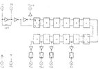
I found the 5082P datasheet. Only it's in Japanese I believe. Also this diagram.
Looks like IC5 (TC5081P) comes in to play as well. I've just been tracing back on the schematic to anything tied to the blown capacitor I had (C103).

tc5080-2631657532.gif
 

Attachments

  • TC5082P_ETC.pdf
    165.8 KB · Views: 7
  • Like
Reactions: brandon7861
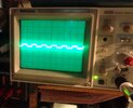
With the scope on pin7 of the 5082P and pin7 of the 2081AP, they connect, I get this image. It's a snapshot, best I can do. But it does appear to have signal unless I'm mistaken. No voltage or freq showing on pin7 though.

DSC03936.JPG
 

Attachments

  • TC5081AP.PDF
    76.5 KB · Views: 2
I found the 5082P datasheet. Only it's in Japanese I believe. Also this diagram.
Looks like IC5 (TC5081P) comes in to play as well. I've just been tracing back on the schematic to anything tied to the blown capacitor I had (C103).

View attachment 68232
I've been looking for that datasheet as well, thank you!

So the 5082 is a divide by N and pin 7 is the /1024 output resulting in 10kHz out for the phase detector (the 5081). You should have 10kHz there.
 
I've been looking for that datasheet as well, thank you!

So the 5082 is a divide by N and pin 7 is the /1024 output resulting in 10kHz out for the phase detector (the 5081). You should have 10kHz there.
I had my counter set to MHz at first, switched to kHz showed the signal frequency. That got me to looking at the data sheet a little more and I see how you got me there. I don't have a very good knowledge of what the ic does, so thanks.

So with all that's going on with the 5082, it looks like everything is there except the 10.24 at pin 1, so that would indicate a possible bad 5082 output of pin 1.

My findings are pin 5 has the 5 volts (VDD), pin 7 has 10 MHz signal, pin 2 and 3 have the 10.24MHz. pin 1 is missing the 10.24MHz.

Or am I missing the boat?
 
Can't find the 5082 data sheet at the moment. Pin 1 should be feeding 10.24 out to L4. Can't receive AM without it. That's a part that rarely fails. Don't know the amplitude pin 1's output should have. Has to be at least a Volt, maybe more?

73
1.047 V, however no 10.24 output on AM-FM.

In the SSB modes I get about 8 MHz @ pin 1.
 
I had my counter set to MHz at first, switched to kHz showed the signal frequency. That got me to looking at the data sheet a little more and I see how you got me there. I don't have a very good knowledge of what the ic does, so thanks.

So with all that's going on with the 5082, it looks like everything is there except the 10.24 at pin 1, so that would indicate a possible bad 5082 output of pin 1.

My findings are pin 5 has the 5 volts (VDD), pin 7 has 10 MHz signal, pin 2 and 3 have the 10.24MHz. pin 1 is missing the 10.24MHz.

Or am I missing the boat?
I assume you meant pin 7 has 10kHz, not MHz. It should be 10kHz.

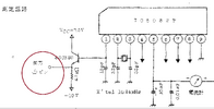
The datasheet suggests that the output on pin 1 has its own buffer, and if that went, it would make sense that the rest of it is (somewhat) working.5082.png
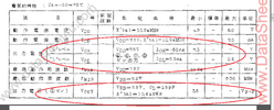
The datasheet also suggests the logic levels coming out of the divider pins should be higher than 1v, more like VDD-0.7v and the voltage on pin 1 should be similar to that with a minimum of 3.5v pk-pk with 7.5v on VDD (graph in datasheet)
5082 2.png
I would guess that chip is toast.

Edit: The picture above shows a circled 1 in the pin description, but I don't know if they mean right at pin 1 (because thats how they show 4, 6, 7, and 8 above it, as circled numbers), but looking closer, they also have a circled 1 at the external buffer output here (I can't read japanese).
5082 3.png
 
Last edited:
I noticed in the schematic that no pull up resistors are used with that chip, so they are internal. Chips with open collector outputs are not so easy to kill, but with internal pull-ups, a slip of the probe tip or contact with an uncovered probe ground ring may have been the cause of the damage, so probe with extreme caution.
 

dxChat
Help Users
  • No one is chatting at the moment.
  • @ Mark Malcomb:
    Hello BJ. Been a long time since I've been on. You doing well? Mark Malcomb
  • @ Naysayer:
    I’m
  • @ kingmudduck:
    Hello to all I have a cobra 138xlr, Looking for the number display for it. try a 4233 and it did not work