• You can now help support WorldwideDX when you shop on Amazon at no additional cost to you! Simply follow this Shop on Amazon link first and a portion of any purchase is sent to WorldwideDX to help with site costs.

RCI 2995DX CF troubleshooting help needed

Ok with the Bias Jumper back in I’m getting 1.7Vdc.
Q65. C 13v. B 2.2v. E. 1.7v. This is new
Q66. C 1.7v. B 13v. E. 13v. This is new
Q67 C 1.7v. B 13v. E. 13v. This is new
Q68 C 8.7v B .5v E 0.5v
Q69 C 13v B -.0 E 0.2V

It looks like that 1.7v is my problem??? Not sure we’re to look for the issue.
 
Last edited:
Yeah. With it plugged back in.

73
Ok with the Bias Jumper back in I’m getting 1.7Vdc.
Q65. C 13v. B 2.2v. E. 1.7v. This is new
Q66. C 1.7v. B 13v. E. 13v. This is new
Q67 C 1.7v. B 13v. E. 13v. This is new
Q68 C 8.7v B .5v E 0.5v
Q69 C 13v B -.0 E 0.2V

It looks like that 1.7v is my problem??? Not sure we’re to look for the issue.
 
I know this is an old post but does anyone know if this has been resolved by any chance? Having a similar issue with voltage at the driver gates and would like to see how this was remedied.

Thanks!
 
Ok with the Bias Jumper back in I’m getting 1.7Vdc.
Q65. C 13v. B 2.2v. E. 1.7v. This is new
Q66. C 1.7v. B 13v. E. 13v. This is new
Q67 C 1.7v. B 13v. E. 13v. This is new
Q68 C 8.7v B .5v E 0.5v
Q69 C 13v B -.0 E 0.2V

It looks like that 1.7v is my problem??? Not sure we’re to look for the issue.
I am no expert, but I read the thread and gave the schematic a look..

When the radio is in SSB, Q69 should be on pulling down the base of Q65 (and thus Q66) which will raise the voltage at the collector of Q66 to about 13v (assuming 13.8v supply). This gives the finals 13v for SSB.

  • Note that you have 13v at the base of Q67 (also the collector of Q69). This tells me that Q69 may have also been cooked. If you have a base voltage on Q69 and there is no voltage on R297 (Q69's emitter resistor), you can call Q69 smoked too. The base of a PNP transistor needs to be pulled .7v lower than the emitter before it starts to conduct (talking about Q67 and Q66 here), and that does not appear to be happening ~ hence the Q69 suspicion.

When the radio is in AM, Q70 turns on and that turns off Q69. With Q69 turning off and its collector voltage going back up, Q65 begins to turn on. Its base voltage (set via the AM PWR trimmer) will set Q67 and Q66 such that the finals see a lower voltage for AM. In this state, the mic audio going through Q65 is able to modulate the regulator base. Q68 controls the modulation depth I believe, but I havent spent too much time staring at that part...
 
  • Like
Reactions: brandon parker
I am no expert, but I read the thread and gave the schematic a look..

When the radio is in SSB, Q69 should be on pulling down the base of Q65 (and thus Q66) which will raise the voltage at the collector of Q66 to about 13v (assuming 13.8v supply). This gives the finals 13v for SSB.

  • Note that you have 13v at the base of Q67 (also the collector of Q69). This tells me that Q69 may have also been cooked. If you have a base voltage on Q69 and there is no voltage on R297 (Q69's emitter resistor), you can call Q69 smoked too. The base of a PNP transistor needs to be pulled .7v lower than the emitter before it starts to conduct, that does not appear to be happening ~ hence the Q69 suspicion.

When the radio is in AM, Q70 turns on and that turns off Q69. With Q69 turning off and its collector voltage going back up, Q65 begins to turn on. Its base voltage (set via the AM PWR trimmer) will set Q67 and Q66 such that the finals see a lower voltage for AM. In this state, the mic audio going through Q65 is able to modulate the regulator base. Q68 controls the modulation depth I believe, but I havent spent too much time staring at that part...
I found this thread because I was searching around on my own problem exact same situation no voltage on the middle pin of q66 and it did end up being Q67 was to blame I swapped it out from a parts radio and it came right back to life I think I popped it in the process of trying an NPC mod I put the diode in incorrectly and ended up popping that transistor I'm happy to report though, that I did get the NPC mod figured out for the 6950 boards and I did it with surface mount devices as well so it looks pimp I'll have to post a picture of it if anybody would like to see it that is lol
 
I found this thread because I was searching around on my own problem exact same situation no voltage on the middle pin of q66 and it did end up being Q67 was to blame I swapped it out from a parts radio and it came right back to life I think I popped it in the process of trying an NPC mod I put the diode in incorrectly and ended up popping that transistor I'm happy to report though, that I did get the NPC mod figured out for the 6950 boards and I did it with surface mount devices as well so it looks pimp I'll have to post a picture of it if anybody would like to see it that is lol
Heck yeah, show us the money. I'm always down to see a pimpin mod!
ResizedP_2cf1fa1e-2ff8-4334-bd7e-5d9ced735a60_144554265295114.gif
 
Heck yeah, show us the money. I'm always down to see a pimpin mod!
View attachment 64057
I got the perfect ringtone for you. Tired of someone choosing the same ringtone as me, I had to have something nobody else had around here with a short alert followed by a short silence giving me time to hit ignore before the rest of the ringtone played.
 

Attachments

  • pimpin aint easy ringtone.mp3
    334.7 KB
I am no expert, but I read the thread and gave the schematic a look..

When the radio is in SSB, Q69 should be on pulling down the base of Q65 (and thus Q66) which will raise the voltage at the collector of Q66 to about 13v (assuming 13.8v supply). This gives the finals 13v for SSB.

  • Note that you have 13v at the base of Q67 (also the collector of Q69). This tells me that Q69 may have also been cooked. If you have a base voltage on Q69 and there is no voltage on R297 (Q69's emitter resistor), you can call Q69 smoked too. The base of a PNP transistor needs to be pulled .7v lower than the emitter before it starts to conduct, that does not appear to be happening ~ hence the Q69 suspicion.

When the radio is in AM, Q70 turns on and that turns off Q69. With Q69 turning off and its collector voltage going back up, Q65 begins to turn on. Its base voltage (set via the AM PWR trimmer) will set Q67 and Q66 such that the finals see a lower voltage for AM. In this state, the mic audio going through Q65 is able to modulate the regulator base. Q68 controls the modulation depth I believe, but I havent spent too much time staring at that part...
I found this thread because I was searching around on my own problem exact same situation no voltage on the middle pin of q66 and it did end up being 267 was to blame I swapped it out from a parts radio and it came right back to life I think I popped it in the process of trying an NPC mod I put the diode in incorrectly and ended up popping that transistor I'm happy to report though, that I did get the MPC mod figured out for the 6950 boards and I did it with surface mount devices as well so it looks pimp I'll have to post a picture of it if anybody would like to see it
Heck yeah, show us the money. I'm always down to see a pimpin mod!
View attachment 64057
Fell off to Dreamland before I saw that I'll post a picture of it shortly.good morning folks
 
I found this thread because I was searching around on my own problem exact same situation no voltage on the middle pin of q66 and it did end up being 267 was to blame I swapped it out from a parts radio and it came right back to life I think I popped it in the process of trying an NPC mod I put the diode in incorrectly and ended up popping that transistor I'm happy to report though, that I did get the MPC mod figured out for the 6950 boards and I did it with surface mount devices as well so it looks pimp I'll have to post a picture of it if anybody would like to see it

Fell off to Dreamland before I saw that I'll post a picture of it shortly.good morning folks
Heck yeah, show us the money. I'm always down to see a pimpin mod!
View attachment 64057
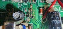
So normally swing mods on these smd radios from what I've seen anyways.... Don't look very good. I wanted to go for a cleaner look all smd and it was fun looking through schematics and searching down the parts I needed but in smd form. Now R292 has been moved and actually isn't present in this picture as I'm playing with different values. But it's d and it mounts directly in the middle of the junction of C313 and C258 and the right side of where R292 is supposed to be I've cut that trace and used that spot as the series junction for the 1SS355 diode and the 100ohm resistor.it isn't in its finished state at all this is just premature celebration because it works so well and I'm still very much learning. Just excited lol
 

Attachments

  • 20230606_113243.jpg
    20230606_113243.jpg
    1.2 MB · Views: 66
So normally swing mods on these smd radios from what I've seen anyways.... Don't look very good. I wanted to go for a cleaner look all smd and it was fun looking through schematics and searching down the parts I needed but in smd form. Now R292 has been moved and actually isn't present in this picture as I'm playing with different values. But it's d and it mounts directly in the middle of the junction of C313 and C258 and the right side of where R292 is supposed to be I've cut that trace and used that spot as the series junction for the 1SS355 diode and the 100ohm resistor.it isn't in its finished state at all this is just premature celebration because it works so well and I'm still very much learning. Just excited lol
Also there is some excess solder on the big trace there due to the learning curve but in the future I know everything I need to know now and won't have to be messy. Good thing this one's a Freebie that was salvaged after being left outside by a fool. Works amazing though and I have a strap on amp for it "this is the 69ffb4" I have two of the amps tho so I'll be finding another radio to truckerize as well. I'd like to find a Stryker to slap that other amp section on.
 
  • Like
Reactions: Shadetree Mechanic
I found this thread because I was searching around on my own problem exact same situation no voltage on the middle pin of q66 and it did end up being 267 was to blame I swapped it out from a parts radio and it came right back to life I think I popped it in the process of trying an NPC mod I put the diode in incorrectly and ended up popping that transistor I'm happy to report though, that I did get the MPC mod figured out for the 6950 boards and I did it with surface mount devices as well so it looks pimp I'll have to post a picture of it if anybody would like to see it

Fell off to Dreamland before I saw that I'll post a picture of it shortly.good morning folks
First of all, glad you found the site and that it took you to getting your radio running. This place is a gold mine, tons of knowledge in here.

I fell of to snoozeville myself so my fire time checks in today.

I'm not much of a swing mod type but nice to see folks persevere in the smd world we now live in. Practice makes perfect my friend and looks good. You should see some of Bell's solder work in an smd board, you'd see that you're doing pretty good!

Thanks for sharing the pimp mod!
Hey thank you for the kind words my friend. I love WWDX its great. For the longest time I couldn't read a schematic and I'm happy to be that far now lol. I have many things I plan on sharing as I get them dialed in. My 2290 final in any radio mod is gonna be a hit I know it! Have a great day 828! Dr. Greenthumb south central Maine
 

dxChat
Help Users
  • No one is chatting at the moment.
  • @ Wildcat27:
    Hello I have a old school 2950 receives great on all modes and transmits great on AM but no transmit on SSB. Does anyone have any idea?
  • @ ButtFuzz:
    Good evening from Sunny Salem! What’s shaking?
  • dxBot:
    63Sprint has left the room.
  • dxBot:
    kennyjames 0151 has left the room.