Ah, okay. So what's wrong with this picture?

This is the tester we use to match Vth every batch of IRF520 and FQP13N10 parts.
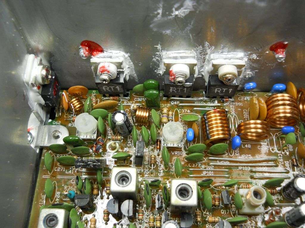
Yes, it's a new unused RT1 MOSFET.

And yeah, both the testers like this one that we use show the same result.

My intuitive guess is that the gate-voltage threshold is just a little higher than the max voltage this thing can feed into it.
I gator-clip lead cobbled a test that showed the transistor was functioning okay. No, I didn't try to calibrate the actual Vth. Just wanted to know if it was likely to work in the radio.
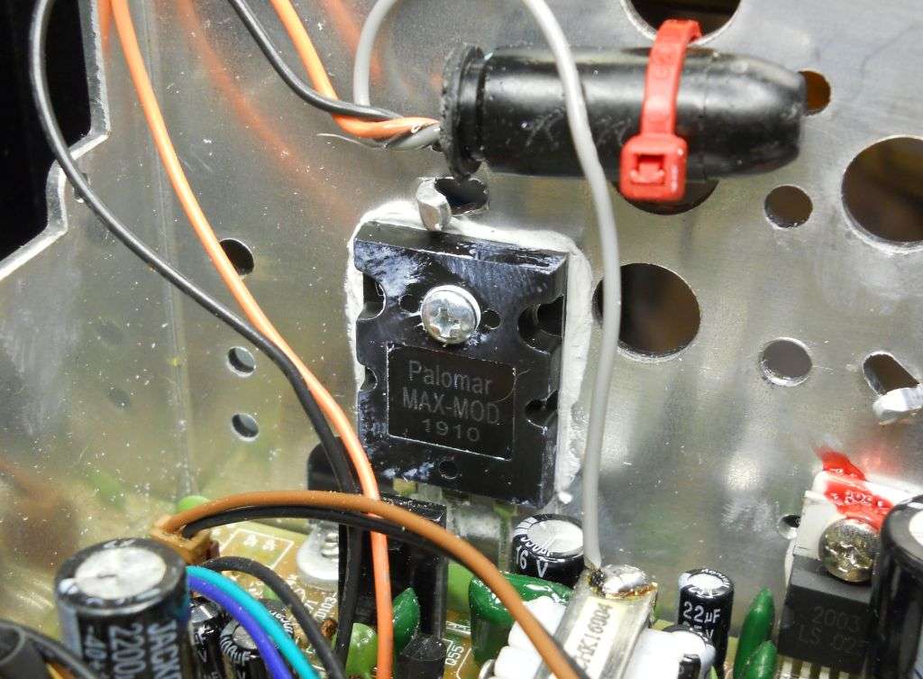
Of course, this customer provided the parts and requested we replace the blown finals and driver in this radio. Sure enough, the originals were bad, and they had clobberred the modulator/reg transistor. Changed them and....
Nothing. Nada. Only the weakest signal leaking out into an adjacent radio.
Naturally, the radio has no drive whatever feeding into the driver when you key the mike. Murphy never sleeps.
It's like Roseanne Rosannadanna used to say, "It's always somethin'".
73
This is the tester we use to match Vth every batch of IRF520 and FQP13N10 parts.
Yes, it's a new unused RT1 MOSFET.
And yeah, both the testers like this one that we use show the same result.
My intuitive guess is that the gate-voltage threshold is just a little higher than the max voltage this thing can feed into it.
I gator-clip lead cobbled a test that showed the transistor was functioning okay. No, I didn't try to calibrate the actual Vth. Just wanted to know if it was likely to work in the radio.
Of course, this customer provided the parts and requested we replace the blown finals and driver in this radio. Sure enough, the originals were bad, and they had clobberred the modulator/reg transistor. Changed them and....
Nothing. Nada. Only the weakest signal leaking out into an adjacent radio.
Naturally, the radio has no drive whatever feeding into the driver when you key the mike. Murphy never sleeps.
It's like Roseanne Rosannadanna used to say, "It's always somethin'".
73