Its all just a fancy Carrier control circuit. The NPC does the same if you watch the DC bias closely on the scope, I believe you can almost see it on a DMM. Careful on which NPC were talking about. The "heavy swinger" version mimmicks SSB to my eyes but it does some weird "surge key" stuff. Dangerous for big box guys, found that out with my box guy and I replaced all his NPC mods with a much safer one.I’ve always wanted to know what was in that TGM under that epoxy or whatever they coat it with.

You are using an out of date browser. It may not display this or other websites correctly.
You should upgrade or use an alternative browser.
You should upgrade or use an alternative browser.
-
You can now help support WorldwideDX when you shop on Amazon at no additional cost to you! Simply follow this Shop on Amazon link first and a portion of any purchase is sent to WorldwideDX to help with site costs.
-
A Winner has been chosen for the 2026 July 4th Retevis RA89R Giveaway! Click Here to see who won!
Realistic TRC-427 Audio Mod 'GoldFinger'
- Thread starter LeapFrog
- Start date
Yes, there seems to be several variants of a process.
(This is Tentative in definition but I need it as a starting point.)
One - Controlled Carrier
Two - Envelope Control
Three - Negative Peak Compression
Each one applies audio to sidebands - however, all have limitations due to the Carrier and Carrier to Envelope and Bandwidth in between.
The main stigma is the bandwidth required.
Controlled carrier you get filtering and the distortion products embedded into the audio Bias line sent to the Final and Driver. The Distortion comes from the limitations of bandwidth dealing with a Modulator using inductance as the main component to modify a DC Power - value into a phase power vector relationship that is obtain by imposing Audio with some considerable drive level to force the inductance to modify DC and the Audio AC - into a complex form of signal that is applied to the Collectors of Driver and Final - Plate modulation as it is sometimes called. The Driving force to obtain the frequency of interest is provided by the Class D application of RF signal to the Driver and the waveform of Collector plus Base from Driver is then applied to Base of Final at the same moment more of this "Plate Modulation" is applied to keep symmetry. Even versus Odd Harmonic productions can be eased by the phasing of Driver and Final Plate Modulation application.
Envelope control is similar to the Controlled Carrier - only the envelope (a sampled filtered and modified to provide an RMS value) power is used to determine carrier power presence. The application can be done linearly as a DC voltage change - but uses a sample of Audio to obtain the power change within the envelope to provide a control signal as much like a JIT or Throttle control to modify the RF signal to increase carrier power as needed to allow the impression of extra audio power into the waveform at instantaneous times to offset the potential distortion product of clipping or saturation events.
Negative Peak Compression is just that - a process to limit negative power from approaching cutoff or near cutoff levels - think of it as below ground reference (Neutral) but also affects the carrier power presence and it's limitation of power applied being 1/2 a supply rail and current limitations of the TX strip.
If I have the above right - let's go - else I'd like a walk thru to see more of the "house" before we put this to market...
I'd have to agree with Andy. If you walk your signal through the "Ranger" darlington modulator. The signal flips phases a few times and by the time it comes back its in phase and is again kinda sampled across the first transistor kinda like a feedback loop to control the original signal. Its the sampling action that varies the bias and changes the carrier of the signal. I think of it as a form of AGC of sorts. I'm not one to market anything lol just a window shopping Tim "the Toolman" TaylorYes, there seems to be several variants of a process.
(This is Tentative in definition but I need it as a starting point.)
One - Controlled Carrier
Two - Envelope Control
Three - Negative Peak Compression
Each one applies audio to sidebands - however, all have limitations due to the Carrier and Carrier to Envelope and Bandwidth in between.
The main stigma is the bandwidth required.
Controlled carrier you get filtering and the distortion products embedded into the audio Bias line sent to the Final and Driver. The Distortion comes from the limitations of bandwidth dealing with a Modulator using inductance as the main component to modify a DC Power - value into a phase power vector relationship that is obtain by imposing Audio with some considerable drive level to force the inductance to modify DC and the Audio AC - into a complex form of signal that is applied to the Collectors of Driver and Final - Plate modulation as it is sometimes called. The Driving force to obtain the frequency of interest is provided by the Class D application of RF signal to the Driver and the waveform of Collector plus Base from Driver is then applied to Base of Final at the same moment more of this "Plate Modulation" is applied to keep symmetry. Even versus Odd Harmonic productions can be eased by the phasing of Driver and Final Plate Modulation application.
Envelope control is similar to the Controlled Carrier - only the envelope (a sampled filtered and modified to provide an RMS value) power is used to determine carrier power presence. The application can be done linearly as a DC voltage change - but uses a sample of Audio to obtain the power change within the envelope to provide a control signal as much like a JIT or Throttle control to modify the RF signal to increase carrier power as needed to allow the impression of extra audio power into the waveform at instantaneous times to offset the potential distortion product of clipping or saturation events.
Negative Peak Compression is just that - a process to limit negative power from approaching cutoff or near cutoff levels - think of it as below ground reference (Neutral) but also affects the carrier power presence and it's limitation of power applied being 1/2 a supply rail and current limitations of the TX strip.
If I have the above right - let's go - else I'd like a walk thru to see more of the "house" before we put this to market...
Yes, no marketing going on.
The schematic is being released for everyone.
I am typing up a basic install procedure, and a F.A.Q. page.
I don't think CB Phreaker is trying to market this either..
I asked him about that some time ago, I don't think he even has any PCB's set aside "for sale".
Everyone I've talked to who has a PCB has received the board free of charge.
I'll ask him about his PCB artwork, because that takes a long time to put together and I won't be handing it out if he doesn't want me to. But anyone with some copper boards, a laser printer, an clothes iron and HCL or Ferric Chloride can etch one at home following the schematic.
I'm not making any guarantees, or promises.
If people use what I put out there, great!
But if they build it and are not satisfied for whatever reason, that's on them. This is a project dedicated to the DIY'er, who is trying to do something cool by themself without paying an arm and a leg to do it.
One more thing, before I create the dedicated thread....
Little over two years ago I couldn't explain what a squelch function was, I had zero experience.
I have had no formal post-secondary education, I don't claim to be an expert.
I have not had a chance to get my tech license, though I'm confident I'd pass.
So with that being said...
I will probably encounter some questions that I may not be able to confidently answer on my own, but I will try my best.
At about two years tinkering with electronics, I really am not "advanced".
Without CB Phreaker Elmering me through this project, I wouldn't be where I am today.
Did he take a high-school graduate and transform him into an RF expert, no, but he did help me time and time again when I was met with failure. I kept trying and kept asking questions..
I feel like he is done with this project, he obviously has more education and knowledge in radio than I do, but yeah the ball is in my court... so to speak.
So without anyone holding my hand, I'm prepared to be embarrassed, laughed at, ridiculed, or worse.
You only live once, but a coward dies a thousand deaths.
Don't feel bad - I'm just as nervous...
That last time I worked on any sort of Asymmetrical thread, the site it was on, crashed...
That last time I worked on any sort of Asymmetrical thread, the site it was on, crashed...
That makes two of us...So without anyone holding my hand, I'm prepared to be embarrassed, laughed at, ridiculed, or worse.
You only live once, but a coward dies a thousand deaths.
711 don't build that PCB and expect it to function correctly without some minor modifications, that is a very early PCB, one of the "Alpha" builds and that design is not printed anymore.
But with enough time and a solder iron you can make it work, just warning you that, that PCB has errors.")
I'm still going to create a dedicated thread, I'm very busy but it will happen.
But with enough time and a solder iron you can make it work, just warning you that, that PCB has errors.
I'm still going to create a dedicated thread, I'm very busy but it will happen.
I have not had a chance to get my tech license, though I'm confident I'd pass.
I'd be surprised if you didn't pass.
")
Hello board, this my second post here and im really trying to get into hifi and I have a question for handy andy about the controlled carrier. I could hardly understand what all about vectors and phase so I looked it up and found a nice definition
Controlled carrier is a modulation system in which the carrier output varies with the audio level, instead of remaining constant as in conventional modulation systems.
I copied that from a magazine here
https://www.americanradiohistory.com/Archive-Radio/30s/Radio-1935-03.pdf
I understood the part about envelope control and negative peak limiting but I want to make sure that I understand the idea behind controlled carrier part.
Thanks in advance.
Correct!
You essentially have to develop a method to IMPOSE, IMPRESS, COMPRESS (you decide the emphasis) a range of frequencies into the Sidebands (Upper and Lower) using Carrier - as the entity, the Audio being properly filtered due to EMPHASIS (Or in the case of Bass response DE-emphasis to prevent an FM/Phasing correlation problem) The carrier is not fixed, but is a dynamic DC bias derived power- that it's power is changed as you apply audio - the major problem within the Audio envelope is in selecting the right base frequency of audio - not just the range of tone - but it's peak response within the tonal range selected.
Then that audio power is a given level of GAIN the carrier needs to add power level to itself to keep the Audio Envelope in proper symmetry (asymmetry is the given effort of the carriers' change of power) and also to maintain frequency of interest.
Once the symmetry from the asymmetry of carrier power in relation to the audio envelope and it's bandpass is determined as the means then, to control the carrier thru a varying Audio / RMS /AVG derived (you pick) signal is understood. The controlled carrier power level variance is what keeps the "Negative swing" at bay - for the envelope then never achieves cutoff nor does it have saturation artifacts either - that is the ideal amplifier concept anyways...
thank you handy andy. Ill try to keep my basic questions at bay, but for the life of I just couldn't figure out what you meant in the first explanation, not that its bad not at all its my lack of understanding. I am in my 2nd semester of electronics and have joined a local ham group so I hope to learn much more. But thanks again any information is appreciated.
Welcome to WWDX...
There's a lot to be said about Asymmetry and "Hi-Fi" - you can't give one 20-20,000Hz resolution - there is simply not enough bandwidth to handle that - Heck even the FM stations use a 19kHz Pilot signal that has to be filtered out, thru the radio - but it is needed to tell the system that there is more info on the other side of this frequency that contains one channel ONLY - that can be used to remove the combined channels in the initial listener frequency (L+R) and leave the difference. (L-R) - so L is "removed" from one to leave R) Else without that processing the FM station would only be heard with L+R as Mono.
With the above in mind that is only FM, as a Frequency Change at an Audio Rate. Carrier stays steady - information moves in around it as shifts in frequency of that carrier but not it's power level.
Amplitude Modulation is similar but the Carrier is pre-set level of power and is NOT able to change frequency - but it's "envelope" can but with Audio - there is only so much spectrum to have information made available. With AM it's even less...and with CB even lesser (SIC) so for the Lessest (SIGH) we make of the effects of Hi Fi and expectations - we can at least achieve information applied to the carrier that rises and falls at a specific rate of change as a POWER LEVEL - the audio information then imposed on it is what appears as asymmetry - it's not - it is the carrier power that does this effect.
That is one way to approach this - others as you have read and seen their efforts - make use of a carrier bias power but change the rate in which that power is made available at any given moment thru the use of a Diode and Resistor and call it NPC, or Negative Peak Compression.
To understand that you need to know of how a regulator works and how the feedback principle of the regulation process works. The Resistor and Diode in the NPC mod, changes the way the "sense" and feedback works in the AM Regulator circuit. It affects how the power given to the Final and Driver as a DC Bias - carrier - gets replenished - which in turn - shows up as negative going power levels - falling levels of power - which the audio that needs to be impressed upon it - uses.
In a typical AM Regulator system - a mid-point is determined and a DC value is derived from it - using either a resistor divider system, or a tapped pre-set voltage regulation system that supplies the power to make the Set-point - or AM power (trimmer pot in a radio) work to make the "steady state" of DC a level of carrier in which to make the Audio power arriving from the Mic Amp section to mix with and develop and envelope of power from.
Note the use of the above to keep it within limits - requires a feedback principle - else if you try to impose too much audio - without feedback - you don't have any means to detect and correctly adjust carrier for the extra audio power needed to be placed in the sidebands - that's where the regulator needs to "sample" the output to adjust for more input of audio power and reserve for application of those audio peaks that would otherwise distort and clip in the efforts the regulator is trying to send to be transmitted along with the carrier - for if it is not kept in check - excessive bandwidth and or audio power applied, causes another effect of; Phase modulation - where the carrier is now mixing with a bunch of frequencies and cannot locate or find stability in any sort way because there is little to no presence of DC bias to keep carrier (Zero point) present.
A way to fix that...

So in a way, NPC is a way of helping to keep bias from dropping too low and audio running into a problem of not having enough carrier to help it generate that envelope.
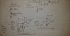
But then, there is this - a typical design using 8 V DC regulated as your means to set mid-point...

From a PC-122 - basic building block shown...
NPC is two parts soldered in series (one lead of one to one lead of another) and installed across the output sense section of the above circuit.
But you lose 1/2 your audio in NPC environments. How, by the loss of the "negative" or down-ward slope or lower voltage than pre-set "carrier AM POWER" - it (Any reserve) drains off into the Output of the Regulator to the Final and Driver - once the AC value of audio as a frequency is converted to this Bias + Audio waveform that gets sent to the Transmitters Final and Driver - it never gets returned - you have to wait a given amount of time for it to replenish from the REGULATION's own supply source. (Your Diode and Resistor - the Diode is that one way valve that keeps power flowing only one way - in this case - out - the Resistor slows down the rate of discharge to a given level of time-slope so you can get some negative "dip" but not much).
Ok, I've gotta stop here for now, too much else is going on but I wish you the best - I am and will be out here, just needs of the family are pretty high on my priority list right now.
There's a lot to be said about Asymmetry and "Hi-Fi" - you can't give one 20-20,000Hz resolution - there is simply not enough bandwidth to handle that - Heck even the FM stations use a 19kHz Pilot signal that has to be filtered out, thru the radio - but it is needed to tell the system that there is more info on the other side of this frequency that contains one channel ONLY - that can be used to remove the combined channels in the initial listener frequency (L+R) and leave the difference. (L-R) - so L is "removed" from one to leave R) Else without that processing the FM station would only be heard with L+R as Mono.
With the above in mind that is only FM, as a Frequency Change at an Audio Rate. Carrier stays steady - information moves in around it as shifts in frequency of that carrier but not it's power level.
Amplitude Modulation is similar but the Carrier is pre-set level of power and is NOT able to change frequency - but it's "envelope" can but with Audio - there is only so much spectrum to have information made available. With AM it's even less...and with CB even lesser (SIC) so for the Lessest (SIGH) we make of the effects of Hi Fi and expectations - we can at least achieve information applied to the carrier that rises and falls at a specific rate of change as a POWER LEVEL - the audio information then imposed on it is what appears as asymmetry - it's not - it is the carrier power that does this effect.
That is one way to approach this - others as you have read and seen their efforts - make use of a carrier bias power but change the rate in which that power is made available at any given moment thru the use of a Diode and Resistor and call it NPC, or Negative Peak Compression.
To understand that you need to know of how a regulator works and how the feedback principle of the regulation process works. The Resistor and Diode in the NPC mod, changes the way the "sense" and feedback works in the AM Regulator circuit. It affects how the power given to the Final and Driver as a DC Bias - carrier - gets replenished - which in turn - shows up as negative going power levels - falling levels of power - which the audio that needs to be impressed upon it - uses.
In a typical AM Regulator system - a mid-point is determined and a DC value is derived from it - using either a resistor divider system, or a tapped pre-set voltage regulation system that supplies the power to make the Set-point - or AM power (trimmer pot in a radio) work to make the "steady state" of DC a level of carrier in which to make the Audio power arriving from the Mic Amp section to mix with and develop and envelope of power from.
Note the use of the above to keep it within limits - requires a feedback principle - else if you try to impose too much audio - without feedback - you don't have any means to detect and correctly adjust carrier for the extra audio power needed to be placed in the sidebands - that's where the regulator needs to "sample" the output to adjust for more input of audio power and reserve for application of those audio peaks that would otherwise distort and clip in the efforts the regulator is trying to send to be transmitted along with the carrier - for if it is not kept in check - excessive bandwidth and or audio power applied, causes another effect of; Phase modulation - where the carrier is now mixing with a bunch of frequencies and cannot locate or find stability in any sort way because there is little to no presence of DC bias to keep carrier (Zero point) present.
A way to fix that...
So in a way, NPC is a way of helping to keep bias from dropping too low and audio running into a problem of not having enough carrier to help it generate that envelope.
But then, there is this - a typical design using 8 V DC regulated as your means to set mid-point...
From a PC-122 - basic building block shown...
NPC is two parts soldered in series (one lead of one to one lead of another) and installed across the output sense section of the above circuit.
But you lose 1/2 your audio in NPC environments. How, by the loss of the "negative" or down-ward slope or lower voltage than pre-set "carrier AM POWER" - it (Any reserve) drains off into the Output of the Regulator to the Final and Driver - once the AC value of audio as a frequency is converted to this Bias + Audio waveform that gets sent to the Transmitters Final and Driver - it never gets returned - you have to wait a given amount of time for it to replenish from the REGULATION's own supply source. (Your Diode and Resistor - the Diode is that one way valve that keeps power flowing only one way - in this case - out - the Resistor slows down the rate of discharge to a given level of time-slope so you can get some negative "dip" but not much).
Ok, I've gotta stop here for now, too much else is going on but I wish you the best - I am and will be out here, just needs of the family are pretty high on my priority list right now.
Last edited:
20Hz - 20 KHz Would be 4 channels at once.
5KHz between the two sidebands, is 10 KHz wide or one channel.
10 KHz of audio frequency gets you at two channels width.
15 KHz of AF, gets you to 30 KHz wide, or three channels.
and 20 KHz of AF between the two sidebands would have you at 4 channels wide.
An RTL-SDR receiver is great for testing, you can use it as a bandscope, and sample the "on air" audio, even if the station is 32 KHz wide, you record "IQ" files that can be uploaded and ran on a computer running SDR# freeware, even if you don't own the USB dongle you can run the capture files and listen to a sample.
I would venture to say most stations out there aren't setup to receive (and fully appreciate) this type of signal.
I think positive peak expansion is another phrase that can get thrown into the mix here, how ever relevant or not..
The NPC mod is not the way I've the AM regulator configured in my modified Cobra 25 LTD.
Last edited:
This is not the first time I’ve built this circuit, I’m not sure how long you’ve been around on these boards but this is a very old topic as Andy has mentioned. CBtricks has had good long discussions about NPC and also Asymmetry. The Modulator of the PC122 section that Andy has highlighted is the same as CBPhreakers board. Nothing special .711 don't build that PCB and expect it to function correctly without some minor modifications, that is a very early PCB, one of the "Alpha" builds and that design is not printed anymore.
But with enough time and a solder iron you can make it work, just warning you that, that PCB has errors.
I'm still going to create a dedicated thread, I'm very busy but it will happen.
Attachments
Cool, I didn't know that a copy was floating around of his early build.
Yeah I never got an opportunity to join the CB Tricks forum, so I don't know anything about the discussions that took place there.
The modulator more closely resembles what is found in the Grant XL/Cobra 148 GTL, looking at the PC-122XL schematic I couldn't find the familiar NPN Darlington configuration, but it very well could be present in some other configuration using a PNP.
"Nothing special" could be said about any circuit.
But I agree the modulator itself is rather simple.
The idea is to get great audio from an inexpensive radio.
With processing it works a treat.
The rest of what he does is to get more power output.
I'm not releasing his mod process, detailing the work on the RF section, I will just be covering the modulator itself.
For anybody wondering.. the "Darlington modulator" or "series pass modulator" install is not about increasing power of the radio, it's about audio and modulation percentage.
Last edited:
dxChat
- No one is chatting at the moment.