I have a Regency Range Gain that is in excellent condition and freshly recapped. The resistance at the tube pins is spot on and the only resistors with issues were the two at the caps and the 27ohm resistor that runs from the bridge rectifier to the cap; which was blown. All were replaced and the radio is operating correctly with the exception of it only modulates to about 3 watts PEP and not the 10+ watts. I've tried new 6AQ5 tubes as well as a new 12BH7 with no change. It keys a little over 1 watt. It is off frequency a tad ( 27.2037 as opposed to 27.2050). I confirmed steps 2 and 3 of the transmit alignment were correct but I am unable to do 1 and 4. Step 1 is the bandpass adjustment and step 4 is the rf calibration. What might I be missing? Are 1 and 4 enough to cause what I'm seeing? Any help would be greatly appreciated. Thanks in advance!

You are using an out of date browser. It may not display this or other websites correctly.
You should upgrade or use an alternative browser.
You should upgrade or use an alternative browser.
-
You can now help support WorldwideDX when you shop on Amazon at no additional cost to you! Simply follow this Shop on Amazon link first and a portion of any purchase is sent to WorldwideDX to help with site costs.
-
A Winner has been chosen for the 2026 July 4th Retevis RA89R Giveaway! Click Here to see who won!
Regency Range Gain low modulation
- Thread starter Champo
- Start date
I have a Regency Range Gain that is in excellent condition and freshly recapped. The resistance at the tube pins is spot on and the only resistors with issues were the two at the caps and the 27ohm resistor that runs from the bridge rectifier to the cap; which was blown. All were replaced and the radio is operating correctly with the exception of it only modulates to about 3 watts PEP and not the 10+ watts. I've tried new 6AQ5 tubes as well as a new 12BH7 with no change. It keys a little over 1 watt. It is off frequency a tad ( 27.2037 as opposed to 27.2050). I confirmed steps 2 and 3 of the transmit alignment were correct but I am unable to do 1 and 4. Step 1 is the bandpass adjustment and step 4 is the rf calibration. What might I be missing? Are 1 and 4 enough to cause what I'm seeing? Any help would be greatly appreciated. Thanks in advance!
So I went ahead and performed all of the steps for alignment that I could with no change. The voltages at the 6AQ5 tube pins ( V9 and V10) are spot on. There are some issues with the 12BH7 final tube values though. Here are the numbers for it. The first number is the value in the Sam's. The second value is what I have.
12BH7
Pin 1 180vdc : 145vdc
Pin 2 -18vdc : +10vdc
Pin 3 15vdc : 9vdc
Pin 6 13vdc : 14vdc
Pin 7 160vdc : 166vdc
Pin 8 180vdc : 200vdc
I'm not sure if this is important or irrelevant to my issue. Thanks!
Champo,
I believe you should not ignore step 1 of the transmitter alignment as the transformers involved (A17, 18, 19 & 20) are in the RF chain. If those are not "Peaked" or adjusted properly, I don't see you getting step 2 (Adjustment of transformer A21) adjusted correctly-as evidenced by the readings you are seeing on the Grid pin of of V12.
Good Luck.
73
David
I believe you should not ignore step 1 of the transmitter alignment as the transformers involved (A17, 18, 19 & 20) are in the RF chain. If those are not "Peaked" or adjusted properly, I don't see you getting step 2 (Adjustment of transformer A21) adjusted correctly-as evidenced by the readings you are seeing on the Grid pin of of V12.
12BH7
Pin 1 180vdc : 145vdc
Pin 2 -18vdc : +10vdc
Good Luck.
73
David

Champo,
Just answering here first because I saw it in a quick scan here on the forum......

If you can for me.... check all of these power supply voltages... just so that we KNOW we are right. See if you can get the output of the rectifier (the 305) and all of the 4 nodes that branch out from it.
Beyond that, I agree with Dmans. The alignment of the tuned circuits in the XMT strip is critical to getting the RF to the antenna.
At the same time... here is where my knowledge falls short... from lack of experience!
THESE DAYS... most transmit alignments just say to peak the circuits for max output.
THIS procedure....is having you feed a sweep generator in and set the "skirts" of the filters... which ... in a way.... is wise as these are apparently being tuned to pass the whole BAND at 11 Mhz and, I am guessing, that a simple "peaking" might result in a narrow bandwidth resulting in different/lower power output towards one edge or the other.
I am curious..... I did not see what channel you were using to test power.
Could you try it at like... 1 & 23 & 13 or so? That gets both edges of the band and a spot towards the middle. Just looking for a difference that might indicate that the "passband" was not wide enough.
If that is it..... the only way I can think of to get this done...is bounce back and forth between Ch 1 and Ch 23, making each adjustment and see if you can balance the output between the two. IN OTHER WORDS..... YOU are ACTING as the sweep generator.
Other than that... if anyone else has ideas.... I know I would appreciate hearing them myself so that I can boost my knowledge.
EDITED TO ADD: If someone can comment.......
It would seem to make sense to me... that if you set the radio for Ch 13 (middlish of the band) and peaked it..... you MIGHT wind up with a passband wide enough to pass everything. At least ...I would THINK that it would be balanced. The peak in the middle...then out to the skirts on both sides.
Thoughts?????
Just answering here first because I saw it in a quick scan here on the forum......
If you can for me.... check all of these power supply voltages... just so that we KNOW we are right. See if you can get the output of the rectifier (the 305) and all of the 4 nodes that branch out from it.
Beyond that, I agree with Dmans. The alignment of the tuned circuits in the XMT strip is critical to getting the RF to the antenna.
At the same time... here is where my knowledge falls short... from lack of experience!
THESE DAYS... most transmit alignments just say to peak the circuits for max output.
THIS procedure....is having you feed a sweep generator in and set the "skirts" of the filters... which ... in a way.... is wise as these are apparently being tuned to pass the whole BAND at 11 Mhz and, I am guessing, that a simple "peaking" might result in a narrow bandwidth resulting in different/lower power output towards one edge or the other.
I am curious..... I did not see what channel you were using to test power.
Could you try it at like... 1 & 23 & 13 or so? That gets both edges of the band and a spot towards the middle. Just looking for a difference that might indicate that the "passband" was not wide enough.
If that is it..... the only way I can think of to get this done...is bounce back and forth between Ch 1 and Ch 23, making each adjustment and see if you can balance the output between the two. IN OTHER WORDS..... YOU are ACTING as the sweep generator.
Other than that... if anyone else has ideas.... I know I would appreciate hearing them myself so that I can boost my knowledge.
EDITED TO ADD: If someone can comment.......
It would seem to make sense to me... that if you set the radio for Ch 13 (middlish of the band) and peaked it..... you MIGHT wind up with a passband wide enough to pass everything. At least ...I would THINK that it would be balanced. The peak in the middle...then out to the skirts on both sides.
Thoughts?????
Thank you Dmans and Guitar_199. The reason I could not perform step 1 is because I do not have access to a sweep generator or a scope. If there is a work around to that then I will gladly perform step 1. Guitar_199 I will get those measurements and post them here. Thank you both for your replies!
Yeah, that is the part that I am trying to get past myself. Even my big ol' Boonton RF generator doesn't have sweep.
Thank you Dmans and Guitar_199. The reason I could not perform step 1 is because I do not have access to a sweep generator or a scope. If there is a work around to that then I will gladly perform step 1. Guitar_199 I will get those measurements and post them here. Thank you both for your replies!
Guitar_199 here are the values you were after.
300vdc source = 312vdc
270vdc source = 258vdc
180vdc source = 210vdc
150vdc source = 178vdc
On channels 1 and 23 it keys about 3/4 of a watt (modulation is turned down on the mic but up on the radio) and swings to about 3.5 watts with a whistle. Channel 13 keys slightly higher at just shy of 1 watt and swings slightly higher to 3.75 watts with a whistle. I hope this helps.
If there is a work around to that
A $50 Nano-VNA will do it.
73
David
THAT is one Hell of a great thought!!!!!
That thing WILL sweep..... as I have seen mention that is will test filters. Thanks for the reminder!
I need to get one of those things.... as much as I love "dorking with antennas".
Bob
That thing WILL sweep..... as I have seen mention that is will test filters. Thanks for the reminder!
I need to get one of those things.... as much as I love "dorking with antennas".
Bob
A $50 Nano-VNA will do it.
73
David
What mic are you using? That radio will perform best with a high impedance power mic such as a powered D104, or one of the transistorized Turner +2, +3 mobile or base mics. I find that sometimes people install a modern day low impedance dynamic stock mic on some of these old tube rigs because the original mic was either missing or damaged, only to find out later they’re not getting sufficient modulation because of the mismatch.
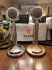
Sunbulls how are you doing? We haven't chatted since that Smokey CB you, guitar_199 and I were troubleshooting! Currently it has an amplified D104 wired to it (the gold one pictured). When I first started troubleshooting it, before committing to this particular D104, I used the cable with the amphenol 91-MC4M 4-Pin connector as an adapter with 2 different amplified D104's, a non amplified D104 and a Turner +3 (all were wired for cobra configurations except the gold D104) to see if any of the mics sounded better on air or produced more swing etc. Both amplified D104's and the Turner +3 produced about 3.5 watts of swing. The non amplified did very little. Keep in mind this was with modulation pot on the radio itself all the way up and the mic pots up a decent ways. Enough so that bleed over was starting to occur in the speaker. That was the only way to get it to go that high.
Attachments
I took voltage readings on all of the tube pins. Tubes were in. The first number is the number in the Sam's. The second number is my reading.
V1
Pin 1 : 45 = 47
Pin 2 : 0 = 0
Pin 3 : 1 = 1
Pin 6 : 80 = squelch open 102/closed 109
Pin 7 : .1 = squelch open -.6/closed -1.2
Pin 8 : 4 = 4
V2
Pin 1 : 260 = 184
Pin 2 : 0 = 0
Pin 3 : 12 = 12
Pin 6 : 260 = 254
Pin 7 : 210 = 206
Pin 8 : -2 = 0
Pin 9 : 8 = 8
V3
Pin 1 : 40 = 20
Pin 2 : 0 = 0
Pin 3 : 1 = 1.5
Pin 6 : 115 = 118
Pin 7 : -6 = -2
Pin 8 : .5 = connection goes to ground
V4
Pin 1 : -2 = squelch open .3/closed -.4
Pin 2 : 2 = 2
Pin 5 : 215 = 226
Pin 6 : 90 = 112
Pin 7 : ground
V5
Pin 1 : -2.5 : .5
Pin 2 : 1.5 =1.5
Pin 5 : 245 = 220
Pin 6 : 85 = 105
Pin 7 : ground
V6
Pin 1 : 0 = 0
Pin 2 : -.2 = -.2
Pin 5 : .4 = .4
Pin 7 : -3.2 = -.6
V7
Pin 1 : 80 = 75
Pin 2 : 3 = 3.6
Pin 3 : 8 = 8.5
Pin 6 : 15 = 15
Pin 7 : ? = keyed 17.2, unkeyed 15.5
Pin 8 : .8 = .9
Pin 9 : 0 = -.1
V8
Pin 1 : 180 = 174
Pin 2 : 70 = 74
Pin 3 : 85 = 89
Pin 6 : 100 = squelch open 99/closed 173
Pin 7 : 45 = 38
Pin 8 : 15 = squelch open 14/ closed .1 closed
Pin 9 : 18 = 16
V9
Pin 2 : 16 = 16
Pin 5 : 290 = 304
Pin 6 : 270 = 260
Pin 7 : 0 = 0
V10
Pin 1 : 0 = 0
Pin 2 : 16 = 16
Pin 5 : 290 = 305
Pin 6 : 270 = 260
V11
Pin 1 : 150 = 130
Pin 2 : -2 = 0 no change transmit/receive
Pin 3 : ? = 13
Pin 6 : 255 = 248
Pin 7 : 190 = 196
Pin 8 : -1 = 0 no change transmit/receive
Pin 9 : 5 = 3.7
V12
Pin 1 : 180 = 143
Pin 2 : -18 = 12
Pin 3 : 15 = depends on loading knob 9-17.3
Pin 6 : 13 = 14
Pin 7 : 160 = 165
Pin 8 : 180 = depends on loading knob 145-200
Last edited:
Champo,
I think I would take a look at pin 1 on both V2 and V12 and see if you can find out why there is such a large difference in schematic vs actual voltage readings. (A bad large wattage resistor in the circuit comes to mind.)
I’m not looking at the schematic at the moment so I’m not sure what V2’s function is but I’m pretty sure V12 is the final output tube.
73
David
V2 is the receive-transmit oscillator and V12 is indeed the final output tube. Disregard the values for V7 as it's wired differently than the Sam's. I double checked it today and I'm going to edit the post with correct numbers. I appreciate the reply and that gives me a direction to look in. Thanks!Champo,
I think I would take a look at pin 1 on both V2 and V12 and see if you can find out why there is such a large difference in schematic vs actual voltage readings. (A bad large wattage resistor in the circuit comes to mind.)
I’m not looking at the schematic at the moment so I’m not sure what V2’s function is but I’m pretty sure V12 is the final output tube.
73
David
V2 is the receive-transmit oscillator and V12 is indeed the final output tube. Disregard the values for V7 as it's wired differently than the Sam's. I double checked it today and I'm going to edit the post with correct numbers. I appreciate the reply and that gives me a direction to look in. Thanks!
So V2 is the 1st and 2nd rec-transmit oscillator and Pin 1 should be 260vdc per Sam's. It appears to be fed by 270vdc (260vdc in my case) to a 22k resistor. The resistor then feeds A10/L12 (ferrite or slug). I have 260vdc on the primary side of that 22k resistor but only 159vdc on the other side of it. The resistor tests good in circuit. I'm not sure how you could expect to in turn have 260v at pin 1 after dropping it coming into A10/L12 without stepping it back up unless I'm misunderstanding this circuit. Unless the Sam's is wrong. V7's wiring is reversed.
Attachments
dxChat
- No one is chatting at the moment.