Have you check Q19 & Q20 on the RF board? Q20 is the per-driver. The RF signal is sent to the Final PA deck via Q19 & Q20 via the T/R relay into the Filter Board. The Filter Board has a number of relays and depending on the band you have selected will depend on which relay is active.Hello, sorry to wake this old thread. I have an output issue on my 430 where I get no output. I tested final transistor vias and removed and tested the output transistors as well. Are there other common failure points on final board. It receives great BTW. No output on any bands.. thanks so much!!

You are using an out of date browser. It may not display this or other websites correctly.
You should upgrade or use an alternative browser.
You should upgrade or use an alternative browser.
-
You can now help support WorldwideDX when you shop on Amazon at no additional cost to you! Simply follow this Shop on Amazon link first and a portion of any purchase is sent to WorldwideDX to help with site costs.
-
A Winner has been chosen for the 2026 July 4th Retevis RA89R Giveaway! Click Here to see who won!
Restoring a Kenwood TS-430S
- Thread starter Radio Tech
- Start date
Restoring a Kenwood TS-430S
A while backed I picked up another HF Radio in on trade. A Kenwood TS-430S. I sat the rig aside thinking the PLL was bad. Radio had no display, receive or transmit. After going through a pair of Swan 500CX’s I decided I needed to start another project. So pulled the 430 apart and...

I know this thread has been ongoing for awhile, hope it still works..
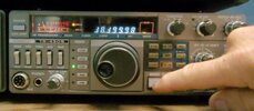
I am getting my old TS-430s up and running again, and the only problem appears to be the display showing sometimes gibberish. It appear to be receiving fine and will tune across the bands, but the display is all messed up. In the process of opening it up and looking for poor solder joints, but was wondering if any one had any advice on where to concentrate my search. Thanks in advance.
Roger")
I am getting my old TS-430s up and running again, and the only problem appears to be the display showing sometimes gibberish. It appear to be receiving fine and will tune across the bands, but the display is all messed up. In the process of opening it up and looking for poor solder joints, but was wondering if any one had any advice on where to concentrate my search. Thanks in advance.
Roger
That is known issue with the 430, I am not sure if parts are still available though.I know this thread has been ongoing for awhile, hope it still works..
I am getting my old TS-430s up and running again, and the only problem appears to be the display showing sometimes gibberish. It appear to be receiving fine and will tune across the bands, but the display is all messed up. In the process of opening it up and looking for poor solder joints, but was wondering if any one had any advice on where to concentrate my search. Thanks in advance.
Roger
I've tried looking around with google searches and can find no similar symptoms. I know the bad solder joints are very common. The encoder seems to be working as I can tune in signals where I expect them to be (using a generator to generate fixed frequency signals) and it appears to tune the spectrum fine, so the encoder data is getting to the rest of the unit and PLL circuits, it just appears to be the actual display, it even affects the channel selector digit, so I am leaning towards the display board wiring from the main control board.
Attachments
Just as an after note, the parts arrived today, and the unit is now appears fully functional. Display is working fine now.
For those interested here is what was involved;
Symptoms: Apparent random display digits.
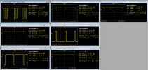
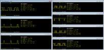
Analysis/Diagnoses: Checked inputs to the display unit, found some pins did not follow the driver inputs. (See images). Driver inputs appeared normal.
Steps: Reflowed all solder joints on display board, checked again, still not right. Checked all board voltages and they all appeared within spec. Determined the driver chip was likely bad. Pulled the chip off the board and tested it on a separate breadboard, found it bad. Ordered a new driver chip. While waiting for chip I decided to solder a DIP socket on the board to facilitate easy replacement.
When the chip arrived, I replaced the chip and display returned to normal! yea! Now I may just do a full RF alignment, although quick spectral measurements appeared within spec.
Symptoms: Apparent random display digits.
Analysis/Diagnoses: Checked inputs to the display unit, found some pins did not follow the driver inputs. (See images). Driver inputs appeared normal.
Steps: Reflowed all solder joints on display board, checked again, still not right. Checked all board voltages and they all appeared within spec. Determined the driver chip was likely bad. Pulled the chip off the board and tested it on a separate breadboard, found it bad. Ordered a new driver chip. While waiting for chip I decided to solder a DIP socket on the board to facilitate easy replacement.
When the chip arrived, I replaced the chip and display returned to normal! yea! Now I may just do a full RF alignment, although quick spectral measurements appeared within spec.
Attachments
dxChat
- No one is chatting at the moment.