• You can now help support WorldwideDX when you shop on Amazon at no additional cost to you! Simply follow this Shop on Amazon link first and a portion of any purchase is sent to WorldwideDX to help with site costs.

Rf Samplers

KD2GOE

W9WDX Amateur Radio Club Member
May 30, 2013
950
219
173
43
Buffalo
Ok I have a few Q's about RF samplers.. what one is right for me? do the type made depend on power output? I only have my tech ticket right now so ill be testing 4 watts too 200 watts, maybe 500 some day when I pass my general exam, so I would like it to have around that range. I do not have a scope just yet I am working on that but that is for a different thread.


I guess there is a few I have seen
Transformer type <<< this seems to be the safest as it is oats the testing equipment from a fault..
RF Sampler 4532.png


voltage divider type
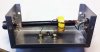
RF Sampler 34368.jpg
 

Attachments

  • RF Sampler 32446.jpg
    RF Sampler 32446.jpg
    31.5 KB · Views: 611
Last edited:

ok I mocked some thing running in to my dummy load and using my MFJ-266. at 5 watts RF I have 344mv at 100 watts I have 403mv @ 7.8mhz I am not Shure if it is taking a peek to peek reading ill have to look in the manual. I would guess if I was running it as 200watts 900mv?

What would a voltage to shoot for so it will be friendly to the Oscilloscope? I am going to guess that may be fine..?
 
The type of sampler in the first picture with the toroid is the preferred type. We used that exact type even on 1 Kw AM transmitters that had audio peaks of over 4 Kw. The size of the toroid is the only real concern. Ideally you could use a small section of coax cable inside the box with the braid broken in the meddle where the toroid is rather than a piece of wire. It just preserves the impedance a little better.The amount of output from it is determined by the number of turns on the toroid. You don't want too much output, a couple volts at most is good.
 
ok I understand the output from it is determined by the number of turns on the toroid. but what would the optimal output?
at 5 watts RF I have 344mv at 100 watts I have 403mv @ 7.8mhz
 
had to remove a resister it was making readings jump all over on my MFJ-266
ill take it over to my friends house he has a scope and ill test it out..

it is molded after a video I seen on youtube


GEDC0450.JPG
GEDC0451.JPG
GEDC0452.JPG
GEDC0455.JPG
 
Voltage out is really dependent on your needs. Some counters require a higher level than others. In general a couple of volts is all you really need. BTW that toroid you have chosen may not work too well. It is yellow/white coded and yellow/white is generally used in switching power supplies and power related circuits at MUCH lower frequencies. It may work but is not the ideal type. Red is better for HF. Try and see. If it works so much the better.
 
Voltage out is really dependent on your needs. Some counters require a higher level than others. In general a couple of volts is all you really need. BTW that toroid you have chosen may not work too well. It is yellow/white coded and yellow/white is generally used in switching power supplies and power related circuits at MUCH lower frequencies. It may work but is not the ideal type. Red is better for HF. Try and see. If it works so much the better.

O ok good to know on the collor coding on the toroid ill keep a look out for a red one...
 

dxChat
Help Users
  • No one is chatting at the moment.