

RM Italy's AD203, "stinger" module looks like a good deal. Until the day it goes poof. This one is in a DAK mark X cabinet alongside a Taiwan Cobra 148 and suitable power supplies. The stinger's heat-sink plate is bolted to the rear panel of the cabinet. There's a standby switch that revealed normal power from the barefoot radio. The owner said it put out about 100 Watts until one day it put out nothing.
The reason this one did just jumps out at you as soon as the pc board is unbolted from the heat-sink plate.
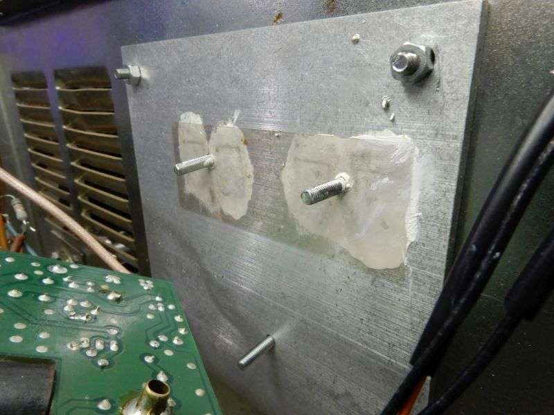
Those wily italians forgot something. You can see a layer of white heat-sink compound between the insulating sheet and the heat-sink plate. But the surface against the MOSFET transistors is dry. Didn't shoot a pic, but the face of each transistor's metal tab is equally dry as a bone.
Once I replaced the MOSFETs with IR-brand IRF520A transistors and a proper layer of compound, I still had a problem. Almost no carrier. A check of the gate bias showed 2.6 Volts. The IRF520s had all shown a Vth of 3.8 Volts when they were checked for matching.
Big deficit here.
Here's the schemo.
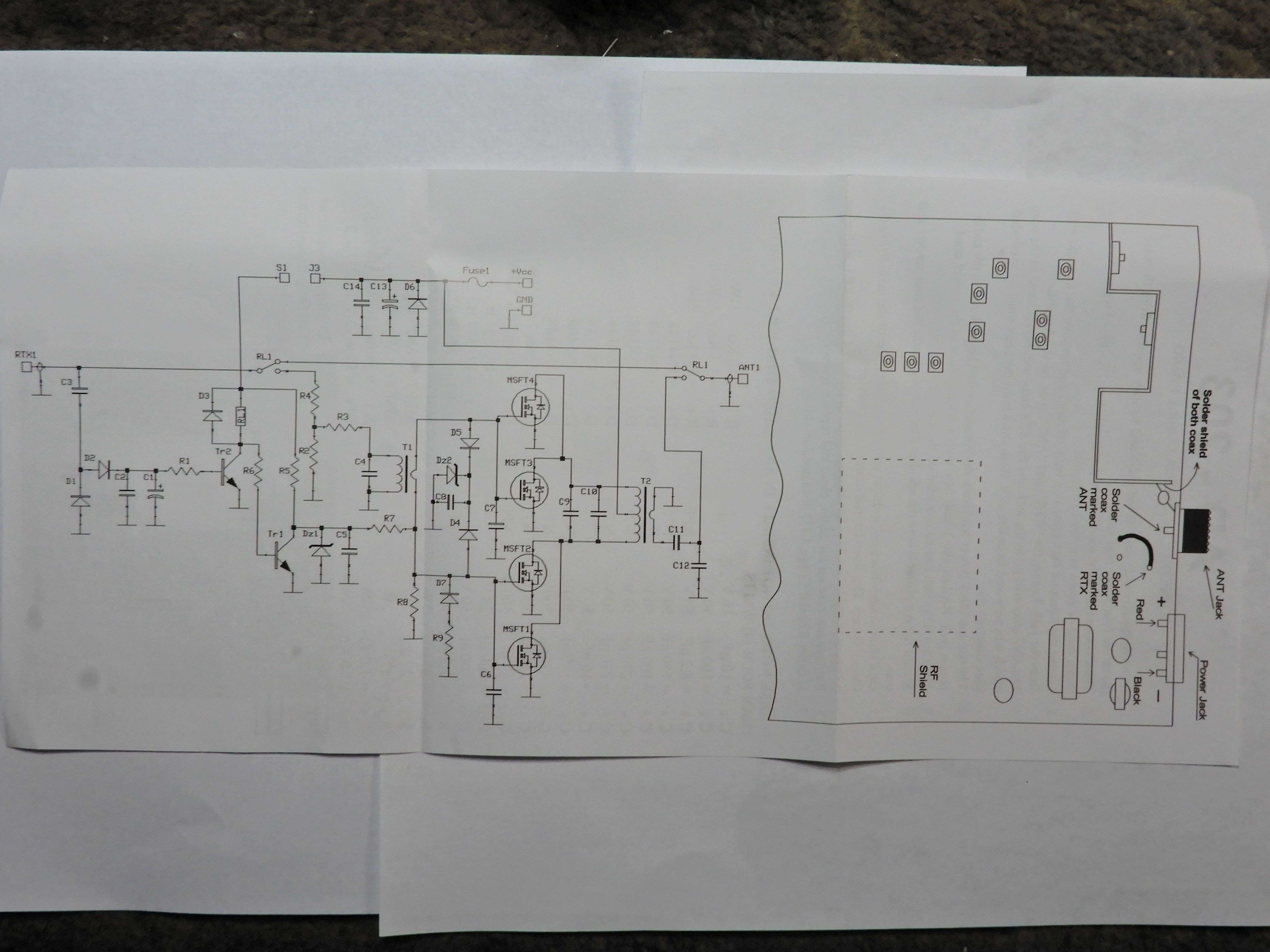
The bias circuit is what needs to be hacked before it will show any power.
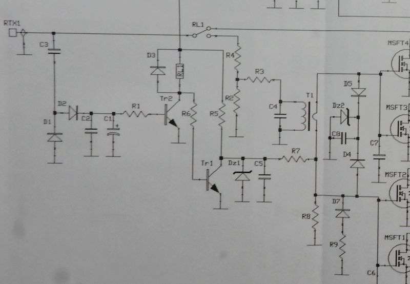
The gate bias is shut off in receive mode by Tr1. It pulls the current through R5 to ground. It gets base current through the relay coil and R6, a 10k resistor. Yes, it gets its base current through the relay coil, just nowhere near enough current to pull the contact lever and go "click". When you key the mike, TR2 connects the cold side of the relay coil to ground and removes the voltage source feeding the base of TR1.
Now that TR1 is turned off, R5 feeds voltage to the 7.5 Volt zener diode DZ1. The 7.5 Volts now feeds into R7, a 10k resistor. R7 feeds into R8, a 3.3k resistor. R7 and R8 divide that regulated 7.5 Volts down to about 2 Volts.
Not enough to turn on the MOSFETs. This explains why a 4 Watt drive carrier from the radio only got me a half Watt out of the Stinger.
The quick-and-dirty solution to increase the gate-bias voltage was to scab a trimmer pot in parallel with R7.
We only need two of the three lugs on a 20k trimpot. Clipping the one we don't need reduces clumsiness. One pin of the trimpot goes to the lower end of R7.
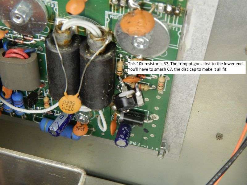
To make it work, the other trimpot lug goes to the end of R8, the 3.3k next to it. That end of R8 and the top end of R7 are connected together in the pcb foil. This was just less clumsy than forcing it onto the upper lead of R7.
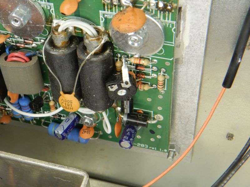
I did not do a proper job of setting idle current with zero drive on sideband. Just set the trimpot for 20 Watts carrier with the radio carrier knob maxed at 4 Watts. Showed 100 Watt peaks, sounded okay on sideband. He's not a sidebander so that wasn't such a big deal.
The numbers were effectively sanded off the original MOSFETs, so I have no idea what they were before they poofed. My suspicion lies with a version of this transistor called the "IRL520". The letter "L" is meant to indicate you can make it switch on with a couple of Volts coming out of a logic gate. The "F" version we used requires a higher DC bias than that. If anybody reading this has tried the "L" version of this part, please share your experience. Seems to be we bought some about ten years ago and never got around to trying them.
73
The reason this one did just jumps out at you as soon as the pc board is unbolted from the heat-sink plate.
Those wily italians forgot something. You can see a layer of white heat-sink compound between the insulating sheet and the heat-sink plate. But the surface against the MOSFET transistors is dry. Didn't shoot a pic, but the face of each transistor's metal tab is equally dry as a bone.
Once I replaced the MOSFETs with IR-brand IRF520A transistors and a proper layer of compound, I still had a problem. Almost no carrier. A check of the gate bias showed 2.6 Volts. The IRF520s had all shown a Vth of 3.8 Volts when they were checked for matching.
Big deficit here.
Here's the schemo.
The bias circuit is what needs to be hacked before it will show any power.
The gate bias is shut off in receive mode by Tr1. It pulls the current through R5 to ground. It gets base current through the relay coil and R6, a 10k resistor. Yes, it gets its base current through the relay coil, just nowhere near enough current to pull the contact lever and go "click". When you key the mike, TR2 connects the cold side of the relay coil to ground and removes the voltage source feeding the base of TR1.
Now that TR1 is turned off, R5 feeds voltage to the 7.5 Volt zener diode DZ1. The 7.5 Volts now feeds into R7, a 10k resistor. R7 feeds into R8, a 3.3k resistor. R7 and R8 divide that regulated 7.5 Volts down to about 2 Volts.
Not enough to turn on the MOSFETs. This explains why a 4 Watt drive carrier from the radio only got me a half Watt out of the Stinger.
The quick-and-dirty solution to increase the gate-bias voltage was to scab a trimmer pot in parallel with R7.
We only need two of the three lugs on a 20k trimpot. Clipping the one we don't need reduces clumsiness. One pin of the trimpot goes to the lower end of R7.
To make it work, the other trimpot lug goes to the end of R8, the 3.3k next to it. That end of R8 and the top end of R7 are connected together in the pcb foil. This was just less clumsy than forcing it onto the upper lead of R7.
I did not do a proper job of setting idle current with zero drive on sideband. Just set the trimpot for 20 Watts carrier with the radio carrier knob maxed at 4 Watts. Showed 100 Watt peaks, sounded okay on sideband. He's not a sidebander so that wasn't such a big deal.
The numbers were effectively sanded off the original MOSFETs, so I have no idea what they were before they poofed. My suspicion lies with a version of this transistor called the "IRL520". The letter "L" is meant to indicate you can make it switch on with a couple of Volts coming out of a logic gate. The "F" version we used requires a higher DC bias than that. If anybody reading this has tried the "L" version of this part, please share your experience. Seems to be we bought some about ten years ago and never got around to trying them.
73
Last edited:
