
You are using an out of date browser. It may not display this or other websites correctly.
You should upgrade or use an alternative browser.
You should upgrade or use an alternative browser.
-
You can now help support WorldwideDX when you shop on Amazon at no additional cost to you! Simply follow this Shop on Amazon link first and a portion of any purchase is sent to WorldwideDX to help with site costs.
-
A Winner has been chosen for the 2026 July 4th Retevis RA89R Giveaway! Click Here to see who won!
Sark 100 antenna analyzer test frequency
- Thread starter Jim5570091
- Start date
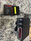


Thanks. I have this manual, maybe my issue with it wasn't fully understood. Look at the picture attached. The sark is showing the test frequency is 40.810 mhz. Connected to a frequency counter it is actually putting out 27.206 mhz. they should match. Right?
I'll have a measure of mine once I recharge the battery.
Havent used it in awhile.
While Im here havea look on https://sm6why.n.nu/sark-100
Havent used it in awhile.
While Im here havea look on https://sm6why.n.nu/sark-100
Good question. I haven't used mine on a single frequency yet. I'm scanning different bands on the antennas I have. In fact I never actually calibrated mine. I attached a 50 ohm dummy load to see what the SARK100 said the ohms were. Then I measured the dummy load with my multimeter, and they were exactly the same. So I called it good.
I know my antenna system is spot on. When I check it @40.810 it’s 49 ohm but 27.205 is off the chart. I built the cal connectors and calibrated it when I first got it. But never figured out the test frequency discrepancy
How did you build the calibration loads? I would like to do this myself.I know my antenna system is spot on. When I check it @40.810 it’s 49 ohm but 27.205 is off the chart. I built the cal connectors and calibrated it when I first got it. But never figured out the test frequency discrepancy
PL259 each resistor value. Solder one lead on center pin and the other to the shield housing. I may or may not have one of them in my parts bin. If I can find one I’ll post a picture.
Does the wattage matter? I have some small resistors I could use, but they're only like quarter watt.PL259 each resistor value. Solder one lead on center pin and the other to the shield housing. I may or may not have one of them in my parts bin. If I can find one I’ll post a picture.
I would verify the tolerance of the resistors are spot on. If you have a dummy load it will work for the 50 ohm

I've just one thing to add here if I may, don't use wire wound resistors for this. I would use high tolerance carbon comp, maybe even metal foil, and if it's just to calibrate the sark or other low power output analyzers, I think 1/4 watt is acceptable, maybe even 1/8 watt.This is how I made my calibration rigs. You just have to get the right combination of resistors to get the correct values. Or order the exact resistors.
View attachment 76564
If using as a dummy load or to set swr indicators on radios (actually connecting it to the radios SO239), you will want the higher wattage resistors, 5 watt comes to mind for short key downs on a stock rig and a higher wattage resistor with good thermal conductance for longer keys or higher output rigs.
Yeah you’re right. For me it was a one time use. And the wire wound was just stuff I had hanging around the shack. But if you know how to get my frequency out put to match the displayed frequency on my sark 100 I would appreciate any suggestions. Look at the attachment at the beginning of the thread.
dxChat
- No one is chatting at the moment.
