I need help i have a shooting star 225+ amp and it has 2 burnt resistor but i am not sure what the color code is on them can somebody tell me were to get a parts break down or schematic for this thanks for your help

You are using an out of date browser. It may not display this or other websites correctly.
You should upgrade or use an alternative browser.
You should upgrade or use an alternative browser.
-
You can now help support WorldwideDX when you shop on Amazon at no additional cost to you! Simply follow this Shop on Amazon link first and a portion of any purchase is sent to WorldwideDX to help with site costs.
-
A Winner has been chosen for the 2026 July 4th Retevis RA89R Giveaway! Click Here to see who won!
shooting star225+ HELP PLZZ
- Thread starter notsodumb101
- Start date
I need help i have a shooting star 225+ amp and it has 2 burnt resistor but i am not sure what the color code is on them can somebody tell me were to get a parts break down or schematic for this thanks for your help
Is this the amp that you have?

.
Unless those two burnt resistors are connected to the Hi / Med / Low power switch, chances are one of the matched pair of RF power transistors is blown open too. Further online analysis would require you post a picture of the inside of the amp showing the locations of the burnt resistors.


Oh, I just had a good laugh looking at the front panel of that transistor amplifier that so proudly displays itself as Class AB1. I wonder how much grid current is flowing in that amp? This should be an indication of the builders knowledge. The numeral 1 that follows the Class AB designation refers to the grid current present during operation. Common sense tells us a solid state amplifier with no tubes or grids can't be Class AB1. The transistor amp could be Class AB if each of the two transistors were biased to conduct over 50% of the sine wave to prevent cross over distortion. It could never be Class AB1.

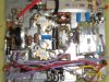
From what I can make out in the pictures I see two possible problems. I can't see a resistor in the location you are pointing to. However, you are right in the spot that a 10 ohm base resistor would be connected to ground. If this is the case, it's a clear indication that the MRF-455 output transistors will need to be replaced. The second issue and probably the cause of the problem in the first place is that it appears the four mounting screws for those two transistors are missing! I see heat sink compound in the center of the holes where screws should be holding them tight to the heat sink to prevent them from overheating and burning out. I just realized you may have the board out, explaining the screws.
yes i have the board out i also took out the 2 resistor out the other 1 goes on the other side of the silver thing hoe can u tell if the 455 is burnt out ? and thanks for your help
If the base swamping resistor you point out is burnt, so is the MRF455 transistor. Under normal conditions the transistor itself provides a load to the incoming RF drive and DC bias. When the transistor base junction burns open, the voltage across this resistor rises and causes it to burn out after the transistor. I'm still not sure where the other two resistors you say are burnt are located. The fact is the one you point out is a 100% indication at least one of the MRF455 transistors are blown. I don't believe they are still in production but can be replaced with the SD1446. They should be replaced as a pair even if only one is burnt out. This insures the circuit runs balanced.


OK, in this case your amplifier uses a pair of 22 ohm base resistors. Red, red, black, color code. They are 1/2 watt and available at Radio Shack. You can purchase the pair of SD1446 output transistor to replace the MRF455's from RF Parts. One thing I notice that is not normal is that both of the 22 ohm resistors are burnt out. This almost never happens in a push pull amp. One out of the two burns up in 99.9% of cases. With both burnt open it indicates a possible problem with the bias.
To confirm a possible bias problem I would connect the amp to a small power supply and no radio. Connect your volt meter negative terminal to ground or the negative side of the power supply. Place the positive lead on the base terminal of the MRF455's. The base is the bottom terminal when reading the print on the part. You will need to jump the keying circuit or take the cover off the relay and manually engage it. If you measure more then 0.7 volts there is probably something wrong with the bias. You may need to replace the pair of 22 ohm resistor before this test depending on the bias circuit.
To confirm a possible bias problem I would connect the amp to a small power supply and no radio. Connect your volt meter negative terminal to ground or the negative side of the power supply. Place the positive lead on the base terminal of the MRF455's. The base is the bottom terminal when reading the print on the part. You will need to jump the keying circuit or take the cover off the relay and manually engage it. If you measure more then 0.7 volts there is probably something wrong with the bias. You may need to replace the pair of 22 ohm resistor before this test depending on the bias circuit.
Same amp
Hi, I just got one of these little amps, it all works somewhat, but I noticed the LOW/MED/HIGH switch does nothing, it stays the same output of about 115 watts on all settings?
Bad switch?
Hi, I just got one of these little amps, it all works somewhat, but I noticed the LOW/MED/HIGH switch does nothing, it stays the same output of about 115 watts on all settings?
Bad switch?
What are the Values of the 2 resistors ( Can be seen on bottom pic above for the Low MED High switch? they are brown and has IRC labled on them) I know they are 5% 2 watt. but need the ohms
I am sorry all I dont think the first set of pic showed my problem here are some better ones i have removed the 2 resistor already i set them back in place so u can see where the go
I need help i have a shooting star 225+ amp and it has 2 burnt resistor but i am not sure what the color code is on them can somebody tell me were to get a parts break down or schematic for this thanks for your help
Surprised no one has asked if the amp still works with the burnt resistors. If one or both of the finals are bad it's time for another amp.
Oh, I just had a good laugh looking at the front panel of that transistor amplifier that so proudly displays itself as Class AB1. I wonder how much grid current is flowing in that amp? This should be an indication of the builders knowledge. The numeral 1 that follows the Class AB designation refers to the grid current present during operation. Common sense tells us a solid state amplifier with no tubes or grids can't be Class AB1. The transistor amp could be Class AB if each of the two transistors were biased to conduct over 50% of the sine wave to prevent cross over distortion. It could never be Class AB1.
Shock, Builders have been sugar coating amplifers by printing AB1 on them for years now BUT..... AB is still cleaner than class C just so people dont missunderstand
")
dxChat
- No one is chatting at the moment.