
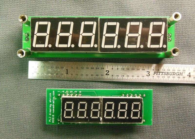
Got a request from a guy in Oz (Australia) who wanted to buy just the shrunk-display part of this toy, not the whole assembled unit. Hadn't really considered that option, but it makes sense. The SanJian PLJ6-LED 6-digit counter display is cheap. And shipping from China to Oz is probably cheaper than shipping from the USA to Down-Under. Finally got decent-size batch of these boards and the digits that fit on it.
In case you missed it, we're removing the nice, big 5/8-inch tall LED 7-segment digits from the SanJian PLJ6-LED 6-digit frequency displays. A piggyback pc board with smaller display digits goes in their place. These are all over ChinaBay, seems like. And they're cheap. The original displays are nice and big. But a bit too big for some radios.
Naturally, once we have installed the smaller digits using our "piggyback" pc board, it will fit behind smaller windows in a radio like the Tram D201, for example.
The stock display digits on this counter are too big for that one.
Seems right to mention some pitfalls to the "DIY" approach.
First, hook up the Fleabay PLJ6 counter you bought and see if all the digits light up. We haven't seen many new ones with defects, but there's no point wasting time to modify a broken counter.
They're cheap. Better to buy two or more for this kind of project.
Next, you might be tempted to clip the leads on the old digits flush against the surface of the counter's pc board. This would leave pins on the old digits long enough to maybe hook up later on. Don't bother.
This is why. Too much risk of nipping pins on the SMT chips. Like this.
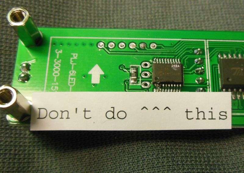
Much safer for the SMT chips to place the dikes flush to the bottom of the display digits. Gets the tool safely above the level of the SMT chips on the pc board.
After you have clipped the pins on the old digits, grip the end of the pin with the point of your small diagonal cutters. Lay the soldering iron against the solder on that pin. When the solder melts, the pin will tip sideways and be easy to pull out of the hole. Just don't pull on it before the solder melts.
Now you need only suck the solder from the hole. This is easier and puts less stress on the pc board than trying to remove enough solder from a hole that has a pin also in it. I found that taking the soldering iron and adding a tiny dab of tin/lead solder to the hole makes it easier to suck it clear with the desoldering iron. Takes only the briefest touch of the iron's tip and a dab of the tin/lead solder.
Seems odd, adding solder to a hole you're about to empty out, but the lead that you add to the lead-free solder already in the hole probably drops the melting temperature. Also could be that the tiny bit of flux you will also add to the hole is helping. All the flux used to solder the original digits in place has been removed with solvent at the end of the manufacturing process. Solder just melts better with flux. The less heat you apply to the foil pads, the less risk of damage to the pc board.
Yes Virginia, the solder pads on the PLJ6 board ARE easy to damage. You'll never guess how I found out.
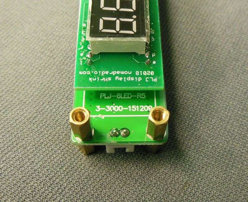
Once the holes are sucked free of solder, there should be no damage to the pads and holes where the piggyback display board will mount. It's worth having a close look first.
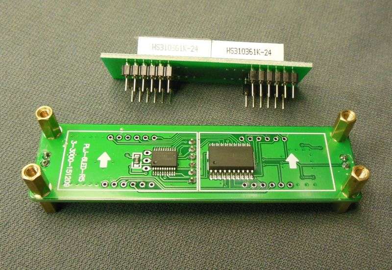
No problem to get it turned around the right way. Won't work upside-down. The screen-printed identification on the piggyback board goes to the end of the PJL6 board that has THEIR screen-printed ID on it.
There is one very-special "gotcha" that deserves mention. Depending on who packaged up the counter you buy, it will have two 2-wire cables, each with a red/black pair of wires with a 2.54mm JST socket on the end. Either both of them will be wired indentically, or THEY WILL WIRED IN MIRROR IMAGE, one will have the red wire on the left pin, the other one with the black wire on the left-hand pin.
Yeah.
So here is the wacky part. If you have the IDENTICAL pair of cables, one will have the black wire to ground on **ONLY** the power socket. Red is plus, black is minus as you see it.
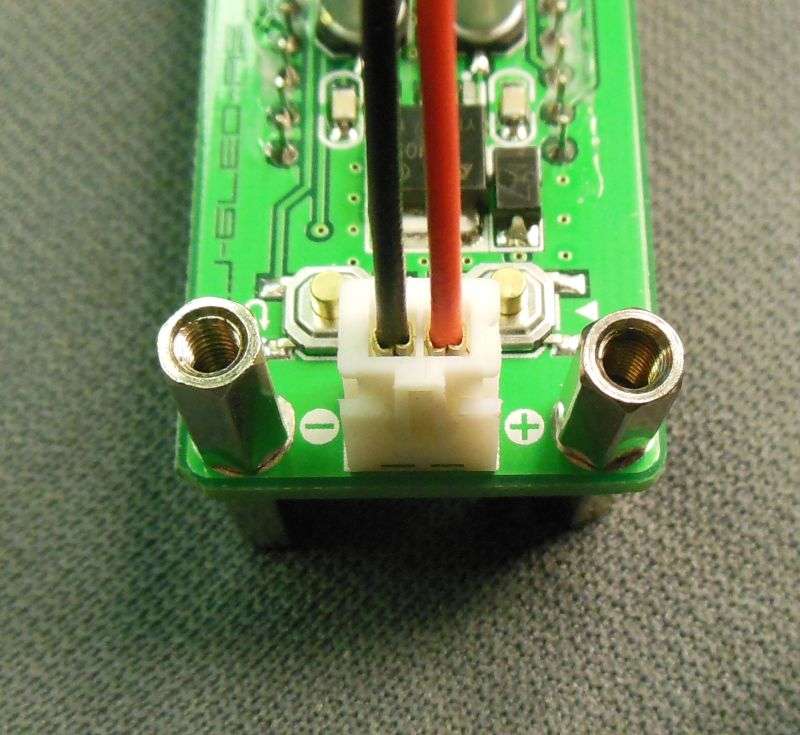
The input socket will find the black wire on the "hot" side, and the red wire to ground.
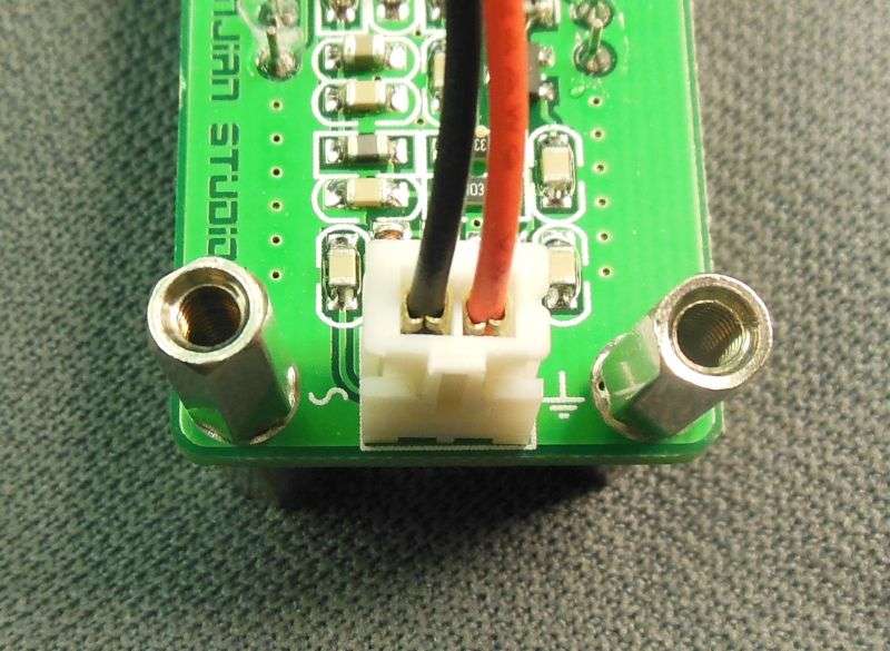
Not a brain buster, but easy to miss if you weren't expecting it.
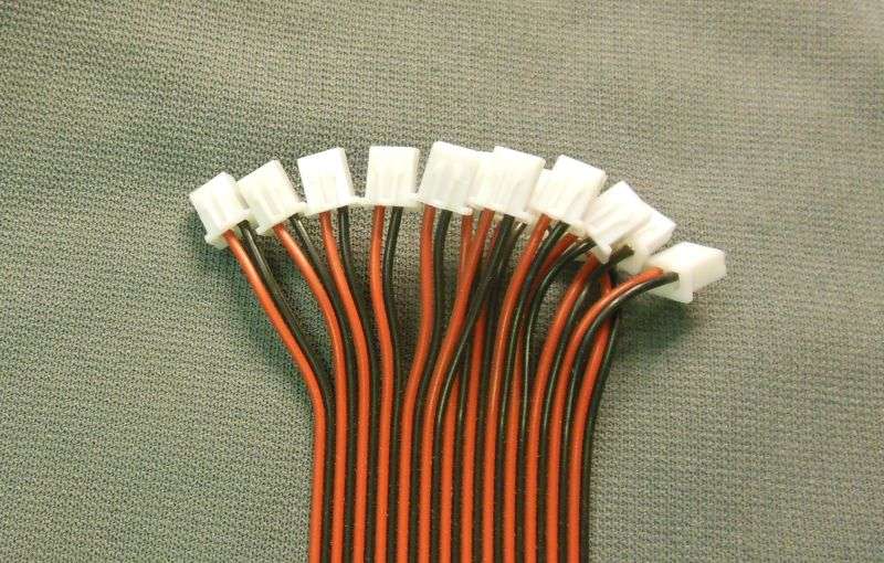
If you buy them in bulk, the cables may be packed separately as a flat array of "married" wires, ready to strip apart. You'll see the red wire is on the left of all these.
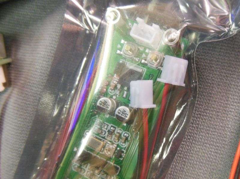
But some of these will have the two cables packed with the counter inside the sealed shiny anti-static bag. So far, all of the mirror-image pairs were supplied this way.
Not the clearest pic I ever shot, but this one was packaged with the mirror-image cables that put the black wire to ground on both sockets. Or the red wire if you swap the two cables.
Just one more thing to watch out for, whether you have two identical cables, or a mirror-image pair.
No,this trick isn't ready for prime time, but it's a lot closer than it was in February.
It might be cheaper to just buy the SanJian PLJ6-LED display and modify it yourself. But only if you don't destroy too many of them in the attempt. Still haven't put a price on the assembled ready-to-install version. Once I add up the labor it takes for the first 25 of them, I'll have a cost figure to base it on.
73
In case you missed it, we're removing the nice, big 5/8-inch tall LED 7-segment digits from the SanJian PLJ6-LED 6-digit frequency displays. A piggyback pc board with smaller display digits goes in their place. These are all over ChinaBay, seems like. And they're cheap. The original displays are nice and big. But a bit too big for some radios.
Naturally, once we have installed the smaller digits using our "piggyback" pc board, it will fit behind smaller windows in a radio like the Tram D201, for example.
The stock display digits on this counter are too big for that one.
Seems right to mention some pitfalls to the "DIY" approach.
First, hook up the Fleabay PLJ6 counter you bought and see if all the digits light up. We haven't seen many new ones with defects, but there's no point wasting time to modify a broken counter.
They're cheap. Better to buy two or more for this kind of project.
Next, you might be tempted to clip the leads on the old digits flush against the surface of the counter's pc board. This would leave pins on the old digits long enough to maybe hook up later on. Don't bother.
This is why. Too much risk of nipping pins on the SMT chips. Like this.
Much safer for the SMT chips to place the dikes flush to the bottom of the display digits. Gets the tool safely above the level of the SMT chips on the pc board.
After you have clipped the pins on the old digits, grip the end of the pin with the point of your small diagonal cutters. Lay the soldering iron against the solder on that pin. When the solder melts, the pin will tip sideways and be easy to pull out of the hole. Just don't pull on it before the solder melts.
Now you need only suck the solder from the hole. This is easier and puts less stress on the pc board than trying to remove enough solder from a hole that has a pin also in it. I found that taking the soldering iron and adding a tiny dab of tin/lead solder to the hole makes it easier to suck it clear with the desoldering iron. Takes only the briefest touch of the iron's tip and a dab of the tin/lead solder.
Seems odd, adding solder to a hole you're about to empty out, but the lead that you add to the lead-free solder already in the hole probably drops the melting temperature. Also could be that the tiny bit of flux you will also add to the hole is helping. All the flux used to solder the original digits in place has been removed with solvent at the end of the manufacturing process. Solder just melts better with flux. The less heat you apply to the foil pads, the less risk of damage to the pc board.
Yes Virginia, the solder pads on the PLJ6 board ARE easy to damage. You'll never guess how I found out.
Once the holes are sucked free of solder, there should be no damage to the pads and holes where the piggyback display board will mount. It's worth having a close look first.
No problem to get it turned around the right way. Won't work upside-down. The screen-printed identification on the piggyback board goes to the end of the PJL6 board that has THEIR screen-printed ID on it.
There is one very-special "gotcha" that deserves mention. Depending on who packaged up the counter you buy, it will have two 2-wire cables, each with a red/black pair of wires with a 2.54mm JST socket on the end. Either both of them will be wired indentically, or THEY WILL WIRED IN MIRROR IMAGE, one will have the red wire on the left pin, the other one with the black wire on the left-hand pin.
Yeah.
So here is the wacky part. If you have the IDENTICAL pair of cables, one will have the black wire to ground on **ONLY** the power socket. Red is plus, black is minus as you see it.
The input socket will find the black wire on the "hot" side, and the red wire to ground.
Not a brain buster, but easy to miss if you weren't expecting it.
If you buy them in bulk, the cables may be packed separately as a flat array of "married" wires, ready to strip apart. You'll see the red wire is on the left of all these.
But some of these will have the two cables packed with the counter inside the sealed shiny anti-static bag. So far, all of the mirror-image pairs were supplied this way.
Not the clearest pic I ever shot, but this one was packaged with the mirror-image cables that put the black wire to ground on both sockets. Or the red wire if you swap the two cables.
Just one more thing to watch out for, whether you have two identical cables, or a mirror-image pair.
No,this trick isn't ready for prime time, but it's a lot closer than it was in February.
It might be cheaper to just buy the SanJian PLJ6-LED display and modify it yourself. But only if you don't destroy too many of them in the attempt. Still haven't put a price on the assembled ready-to-install version. Once I add up the labor it takes for the first 25 of them, I'll have a cost figure to base it on.
73
Last edited:
