
I bought this Siltronix VFO on Ebay with the intention of converting it to the 6-digit LED display we normally use, with a new smoked-plex faceplate.
My customers don't like LCD displays. They like LEDs, they say. My intention all along was to convert it our way.
Just the same, it seemed worth posting a "How Not To" based on this toy.
First clue that this conversion had problems is the displayed frequency.
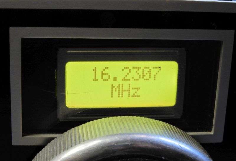
Turns out this counter display is *NOT* the one that lets you program an offset frequency, so it can display the operating frequency.
This one is a straight frequency counter. It only knows how to display the actual frequency you feed into it.
Oops.
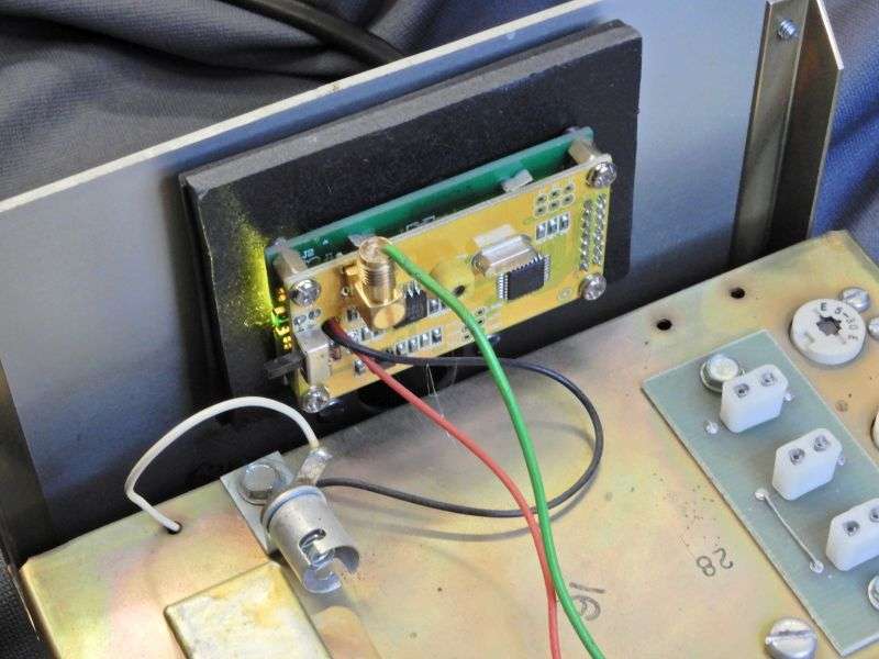
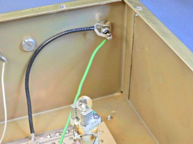
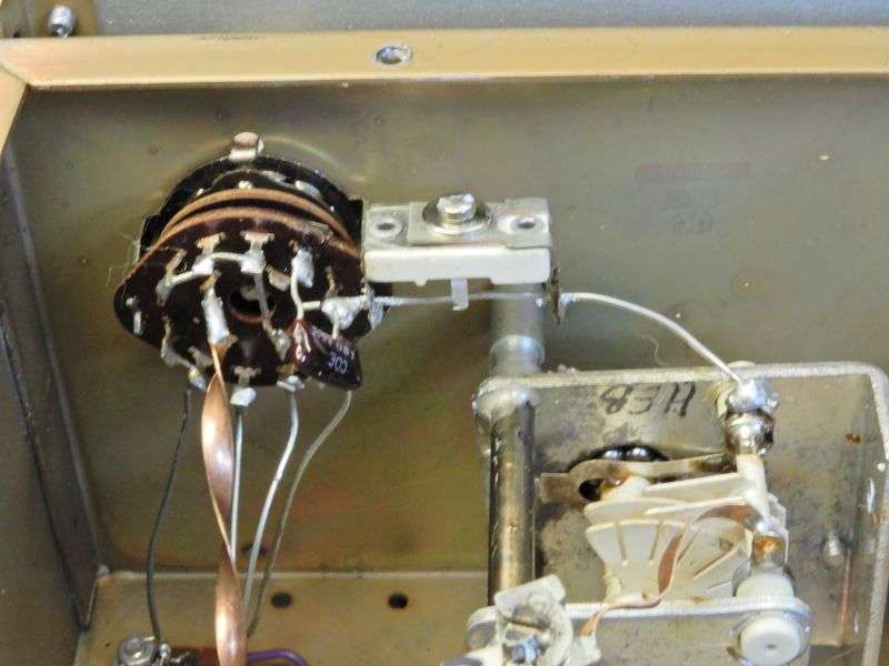
The input hookup is interesting. A simple unshielded wire stuck into the center hole of the SMA socket. We don' need no stinking plug. Or shielded wire either, apparently.
The power hookup is wrong, too. The orange wire is tapped into the zener-regulated 7-Volts that powers the oscillator. Pretty sure there isn't enough spare current to run the display's backlight LEDs. Didn't spend any time to see if this made the drift worse, but it can't help.
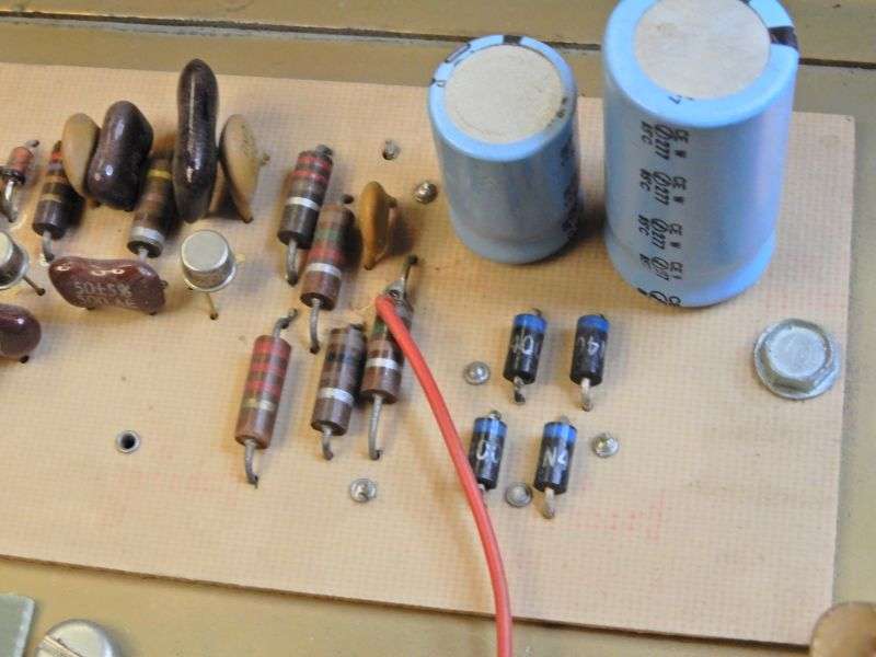
One part of the stock setup we always change is the CB/HF band-change circuit. This trimmer cap is factory-original, but it's the reason the VFO's output level falls in half (or less) when you switch from the "CB" to "HF" band.
But that would bring us from "How Not To" to the "How we do it" post.
Film at 11.
73
My customers don't like LCD displays. They like LEDs, they say. My intention all along was to convert it our way.
Just the same, it seemed worth posting a "How Not To" based on this toy.
First clue that this conversion had problems is the displayed frequency.
Turns out this counter display is *NOT* the one that lets you program an offset frequency, so it can display the operating frequency.
This one is a straight frequency counter. It only knows how to display the actual frequency you feed into it.
Oops.
The input hookup is interesting. A simple unshielded wire stuck into the center hole of the SMA socket. We don' need no stinking plug. Or shielded wire either, apparently.
The power hookup is wrong, too. The orange wire is tapped into the zener-regulated 7-Volts that powers the oscillator. Pretty sure there isn't enough spare current to run the display's backlight LEDs. Didn't spend any time to see if this made the drift worse, but it can't help.
One part of the stock setup we always change is the CB/HF band-change circuit. This trimmer cap is factory-original, but it's the reason the VFO's output level falls in half (or less) when you switch from the "CB" to "HF" band.
But that would bring us from "How Not To" to the "How we do it" post.
Film at 11.
73
