
Recently upgrade my antenna analyzer to a RigExpert AA-650. Have a couple of questions regarding calibration and the Smith Chart using a OSL calibration kit.
First my understanding is that every time you change frequency technically you need to re-calibrate.
Secondly if the electrical length changes so do the plots on the Smith Chart. Which would mean that any variance in manufacturing of the connectors be they of the SO-239 type, Sma or N type results in Pico/Nano changes in the electrical length.
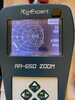
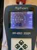
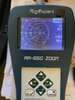
Attached are three pictures showing my Smith Chart plots...open end at the RigExpert, open end 1.5 feet of coax and open end 17 feet of coax. Help me understand what I’m seeing on the three plots.
Now onto calibration questions.
1. For the best accuracy would I need to calibrate by disconnecting the antenna, connecting my OSL (open, short, load) at the end of the coax nearest the antenna feed point?
2. My understanding is that calibrating at the analyzer output point is not where I want the calibration to take place. Would a short piece of coax be best?
3. Obviously this isn’t a military/space/precision setup...only HF/6 meters and UHF/VHF.
4. My take is that the Pico/Nano seconds of change in the electrical length is probably non-consequential when it comes to the frequencies/bands involved.
I’m sure I’ll have other questions along the way.
No I’m not designing antennas just seeking to expand my limited understanding.
Thanks in advance
Brad
KE0XS
South of Pittsburgh
The first picture is using a 17 foot piece of coiled coax.
The second picture is nothing connected to the analyzer
The third picture is using a 1.5 foot pice of coax
First my understanding is that every time you change frequency technically you need to re-calibrate.
Secondly if the electrical length changes so do the plots on the Smith Chart. Which would mean that any variance in manufacturing of the connectors be they of the SO-239 type, Sma or N type results in Pico/Nano changes in the electrical length.
Attached are three pictures showing my Smith Chart plots...open end at the RigExpert, open end 1.5 feet of coax and open end 17 feet of coax. Help me understand what I’m seeing on the three plots.
Now onto calibration questions.
1. For the best accuracy would I need to calibrate by disconnecting the antenna, connecting my OSL (open, short, load) at the end of the coax nearest the antenna feed point?
2. My understanding is that calibrating at the analyzer output point is not where I want the calibration to take place. Would a short piece of coax be best?
3. Obviously this isn’t a military/space/precision setup...only HF/6 meters and UHF/VHF.
4. My take is that the Pico/Nano seconds of change in the electrical length is probably non-consequential when it comes to the frequencies/bands involved.
I’m sure I’ll have other questions along the way.
No I’m not designing antennas just seeking to expand my limited understanding.
Thanks in advance
Brad
KE0XS
South of Pittsburgh
The first picture is using a 17 foot piece of coiled coax.
The second picture is nothing connected to the analyzer
The third picture is using a 1.5 foot pice of coax
")
