Based on a couple posts I made in several different threads, it occurred to me (after a suggestion from Moleculo) that this site could use a thread dedicated to solid-state amplifiers and how to keep their output clean. Maintaining clean output from a station is a foremost obligation of any radio operator and service, regardless of what class of license the op holds or if there is a license required at all.
I don't want to get into too much technical detail here, primarily because it's lengthy and dry and because I'm not an expert on the level where I would feel comfortable providing too much detail. Also, simple explanations are easier for anyone to understand. I'm a hobbyist first and foremost, so everything I share is based on my personal experience, which has been helped along by various texts.
First off let me describe two concepts which define amplifiers: Linearity and Non-Linearity.
Almost everyone in radio has heard RF amplifiers be called (most of the time incorrectly) simply "linear amplifiers". This refers to the ideal condition in which an amplifier provides a completely unmodified, but LARGER in amplitude (more powerful) copy of the input wave.
In reality, no amplifier is perfectly linear. When a wave is input, the resulting output is always altered in more ways than simply being more powerful. This extra alteration is referred to as "non-linearity" or more commonly "distortion". The factor that determines how close to being truly linear an amplifier comes is it's class.
Amplifier Classes:
There are 4 main classes of amplifier (more actually, but 4 for our purposes here): Class A, Class AB, Class B and Class C.
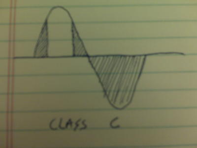
Class C amplifiers are the simplest amplifiers in terms of design complexity. To help describe things a little better I'll refer to the waveform in degrees, with a complete waveform consisting of 360 deg. and partial waveforms as less than 360 deg. If only half of the waveform appears at the output, we would say that the amplifier is conducting 180 deg. of the signal etc.
Every transistor has what is referred to as a "threshold". This is the voltage at which the transistor begins to conduct. By it's nature, a radio signal consists of a train of waves. A wave consists of varying voltages and/or currents. A sine wave, as it pertains to radio, typically has a positive portion (half of the wave consists of positive voltages) and a negative portion (the other half consists of negative voltages). The simplest and most common transistors (BJTs or bi-polar junction transistors) have a threshold of .7V. This means that when a wave is input into a single BJT transistor in the simplest possible amplifier, the transistor only produces output when the input wave is at .7V or higher. Obviously this means that that the rest of the wave (the entire negative portion and some of the positive portion) is missing from the output signal. The amplifier is conducting less than 180 deg. which means most of the original signal is missing. This is a classic example of nonlinearity. We put in a sine wave and we get only part of it back. This chopped up output wave is said to be "distorted". This describes "class C" amplifiers. Even though the output is distorted, class C amplifiers are still very useful, particularly with FM (by it's nature FM is unaffected by a distorted carrier) and collector-modulated AM (more complex and not very common with small brick amplifiers). Class C amplifiers are not suitable for pure AM and SSB usage however, as these modes are very much affected by distortion, causing bad sounding modulation and interference to other equipment and radio operators.
Since the threshold of a BJT transistor is ~.7V, we can help eliminate a lot of this distortion by ensuring that more of the input signal is always above threshold. When more of the input signal is above threshold, we get more of the signal at the output. We accomplish this by adding a DC voltage equal to the threshold directly to the base (input terminal) of the transistor. By adding a .7V DC voltage-only (negligible current) source we are adding what's called "bias". This bias insures that the signal cannot fall below .7V, which means that the entire positive portion of the input waveform will be above .7V, while the negative portion will flat-line at .7V. This gives us exactly half of the original waveform at the output. This refers to a class B amplifier, which conducts exactly 180 deg. of the input signal. Since 180 deg. at the output is more than what a class C amplifier produces, a class B amplifier is more "linear" than a class C amplifier but still leaves much to be desired in terms of linearity.
If we add bias consisting of both a .7V DC source AND a bit of current to go with it, we end up with a class AB amplifier. Since BJT transistors are current-controlled devices, the extra current helps ensure that even more of the input waveform is produced at the output, usually a bit more than 180 deg., which means that the majority (but not all) of the input waveform appears at the output. Obviously this means that a class AB amplifier is more linear than a class B amplifier, so now we are getting to the point where we can use the amplifier with AM and SSB, which require low distortion. Typically a class AB amplifier is the lowest class (in terms of distortion) that can be used with these modes.
Finally, if we add bias consisting of a higher voltage than the threshold (for example 1-2V) along with some current we can reach the pinnacle of low-distortion amplification, class A. The extra voltage and current push all 360 deg. of the input waveform above threshold and therefore the transistor conducts all 360 deg. of the input signal, giving 360 deg. at the output. This produces the lowest possible distortion level, and the cleanest output. Class A amplifiers can be used with any mode or type of signal.
This graphic shows each class along with the portion of the input waveform that is successfully duplicated for each. The shaded areas are what ends up being lost:

After learning the details of the various classes it's easy for a person to think that class C is inferior and class A superior, which leads to the question: Why use anything but class A? The answer is Efficiency: A class C amplifier produces the most distortion, but also has the best efficiency. A class A amplifier has clean output but the least efficiency. As an example, this means that a single-transistor class C amplifier using an MRF455 will produce more power for a given input current than a class A amplifier with the same transistor at the same current level. Classes B and AB fall in the middle of the efficiency curve.
The above pertains to BJT transistors. MOSFET transistors are increasingly popular, and the main difference in terms of class of amplifier using MOSFETs is the fact that a MOSFET's threshold is usually on the order of 5-6V instead of .7V, so even class C MOSFET amps have some bias, and to bias a MOSFET requires higher voltage than a BJT. Also, since MOSFETs are voltage controlled (as opposed to current-controlled BJTs) the bias circuitry is actually simpler to implement.
Now that I've touched on distortion and how it relates to the various amplifier classes, I'll discuss how to clean things up.
There are 2 types of distortion found in RF amplifiers: Intermodulation Distortion (IMD) and harmonic distortion.
IMD is a function of the transistor itself, and most transistor datasheets specify a figure for output IMD at a given input level. IMD is therefore controlled and reduced by proper circuit design in the amplifier itself. A single-transistor amplifier (single-ended) will exhibit the worst IMD performance, and push-pull amplifiers, due to certain variables, help keep it comparatively minimized. Normally the very best way to minimize IMD is to "over-enigneer" the amplifer. Over-engineering means driving components well below their maximum ratings. If you've got a 70W transistor (as in 70W stated in the transistor datasheet) then good engineering would dictate that you only drive it to 50W for low IMD figures and enhanced ruggedness and therefore lifetime. In short, to minimize IMD NEVER overdrive a transistor and always use push-pull designs. A push-pull design uses 2 transistors in tandem, with each transistor helping to fill in the missing portions of the signal that are lost by the other transistor. Between the two transistors we get a fairly good copy of the input waveform.
The second form of distortion is Harmonic Distortion. Harmonics are sub-waveforms that are formed my an amplifier at 2X, 4X, 8X the original frequency etc.. Normally these harmonics can contain a good bit of power, and they occur well outside of the band that the amplifier is intended for. This causes interference in may ways, none of which are good. Fortunately, it's not hard to deal with them. All that needs to be done is to filter them out.
That brings me to filters, which I'll spend a bit of time describing since they seem to be shrouded in a bit of mystique, especially with CB enthusiasts.
Filtering Out Harmonics:
Harmonic filters are usually built from combinations of inductors and capacitors. These components are combined in to fairly simple networks with values that give a specific, desired response.
Here are some circuits and plots that should help demonstrate what harmonic filters are and how they work (made these for a different thread that some folks may already have read):
The red curve is the transmission dB of attenuation, which is the amount of incoming power that makes it through the filter. Any power that does not make it through the filter are losses. The blue curve is the VSWR curve, the high points of which are proportional to the transmission losses as can be seen.
here's a fairly basic 5-pole Chebyshev filter for 30MHz:

and it's transmission/VSWR curves:

You can see some large variation in the input VSWR indicating variations in input impedance which causes losses, heating, and potentially damage within the filter at those operating points where the SWR is high. You can see by the transmission curve (red) that there are slight losses occurring where the SWR is higher. At high power levels, even slight losses add up to a good amount of heating and damaging effects.
Here's the same filter with 2 more poles added, making a 7-pole Chebyshev:

Plots for the 7-pole Chebshev:

You can see that the input SWR across 10-12m is much more acceptable, resulting in less losses and heating at those frequencies.
Here's a whole different animal, a 7-pole Elliptic filter for 30MHz:

and plots for the 7-pole elliptic:

Here you can see that the input SWR is very low across the whole HF band, which makes this a particularly good design, but more complex to build and the power-handling capability is somewhat more limited.
Typically, performance is pretty much always better with more complex filters, within reason of course. That's not to say that simpler filters aren't useful. It's possible with the right math and the right components to have simpler filters (5-pole) with better SWR performance than seen in my example above. Also, more complex filters provide sharper cutoff and in the case of elliptic filters they can even be tuned to suppress specific harmonic frequencies. The transmission curve for the elliptic filter above shows these distinct and sharp suppression spikes after cutoff.
In conclusion, by using good engineering sense when designing or modifying an amplifier, along with well-designed harmonic filters it becomes possible to have an amplifier with good efficiency, very low distortion and therefore very little potential for interference. The bottom line is that this is about maintaining your station's output out of respect for others. Running a station that produces dirty output will almost invariably cause RFI problems across the radio spectrum. Whether you as the station operator are aware of this RFI or not, it is still there, and it is still causing problems for other people, whether it's messing with their phones, TVs, and toasters or bleeding on a public-service frequency used by a local PD or FD. Either way it causes problems, and some of those problems could threaten public service and safety in the worst case.
To put it bluntly, radio operators who only care how many watts they are "putting out" with no regard for whether that power is clean are almost always guaranteed to be interfering with someone else. I've heard and seen a lot of stuff online and on the air about how certain operators feel like people are unfairly calling them out for using poorly built, overdriven class C garbage on AM and SSB, but in reality it is NOT AT ALL unfair that they are being called out. Who likes it when people are so selfish that they don't care about anyone but themselves? NO ONE. That's just a fact of life, not just the radio hobby. That's why responsible, conscientious operators care about these things. The more people that care about proper engineering and good station operating techniques, the less noise and trash there will be on the bands, and the less interference there will be to other systems and neighbors. Obviously that's good for everyone.
Personally I would rather have very low power that is clean than lots of power that is dirty. Even though people might hear me better with gobs of extra juice, it's not worth it to me if it means I'll be causing other people and services grief. Basic "golden rule" stuff here.. not rocket science.
I'll follow up with more info as soon as I have more time regarding the construction of a set of filters, for the purpose of bringing the concepts discussed here regarding harmonic filtering into the real world.
I don't want to get into too much technical detail here, primarily because it's lengthy and dry and because I'm not an expert on the level where I would feel comfortable providing too much detail. Also, simple explanations are easier for anyone to understand. I'm a hobbyist first and foremost, so everything I share is based on my personal experience, which has been helped along by various texts.
First off let me describe two concepts which define amplifiers: Linearity and Non-Linearity.
Almost everyone in radio has heard RF amplifiers be called (most of the time incorrectly) simply "linear amplifiers". This refers to the ideal condition in which an amplifier provides a completely unmodified, but LARGER in amplitude (more powerful) copy of the input wave.
In reality, no amplifier is perfectly linear. When a wave is input, the resulting output is always altered in more ways than simply being more powerful. This extra alteration is referred to as "non-linearity" or more commonly "distortion". The factor that determines how close to being truly linear an amplifier comes is it's class.
Amplifier Classes:
There are 4 main classes of amplifier (more actually, but 4 for our purposes here): Class A, Class AB, Class B and Class C.
Class C amplifiers are the simplest amplifiers in terms of design complexity. To help describe things a little better I'll refer to the waveform in degrees, with a complete waveform consisting of 360 deg. and partial waveforms as less than 360 deg. If only half of the waveform appears at the output, we would say that the amplifier is conducting 180 deg. of the signal etc.
Every transistor has what is referred to as a "threshold". This is the voltage at which the transistor begins to conduct. By it's nature, a radio signal consists of a train of waves. A wave consists of varying voltages and/or currents. A sine wave, as it pertains to radio, typically has a positive portion (half of the wave consists of positive voltages) and a negative portion (the other half consists of negative voltages). The simplest and most common transistors (BJTs or bi-polar junction transistors) have a threshold of .7V. This means that when a wave is input into a single BJT transistor in the simplest possible amplifier, the transistor only produces output when the input wave is at .7V or higher. Obviously this means that that the rest of the wave (the entire negative portion and some of the positive portion) is missing from the output signal. The amplifier is conducting less than 180 deg. which means most of the original signal is missing. This is a classic example of nonlinearity. We put in a sine wave and we get only part of it back. This chopped up output wave is said to be "distorted". This describes "class C" amplifiers. Even though the output is distorted, class C amplifiers are still very useful, particularly with FM (by it's nature FM is unaffected by a distorted carrier) and collector-modulated AM (more complex and not very common with small brick amplifiers). Class C amplifiers are not suitable for pure AM and SSB usage however, as these modes are very much affected by distortion, causing bad sounding modulation and interference to other equipment and radio operators.
Since the threshold of a BJT transistor is ~.7V, we can help eliminate a lot of this distortion by ensuring that more of the input signal is always above threshold. When more of the input signal is above threshold, we get more of the signal at the output. We accomplish this by adding a DC voltage equal to the threshold directly to the base (input terminal) of the transistor. By adding a .7V DC voltage-only (negligible current) source we are adding what's called "bias". This bias insures that the signal cannot fall below .7V, which means that the entire positive portion of the input waveform will be above .7V, while the negative portion will flat-line at .7V. This gives us exactly half of the original waveform at the output. This refers to a class B amplifier, which conducts exactly 180 deg. of the input signal. Since 180 deg. at the output is more than what a class C amplifier produces, a class B amplifier is more "linear" than a class C amplifier but still leaves much to be desired in terms of linearity.
If we add bias consisting of both a .7V DC source AND a bit of current to go with it, we end up with a class AB amplifier. Since BJT transistors are current-controlled devices, the extra current helps ensure that even more of the input waveform is produced at the output, usually a bit more than 180 deg., which means that the majority (but not all) of the input waveform appears at the output. Obviously this means that a class AB amplifier is more linear than a class B amplifier, so now we are getting to the point where we can use the amplifier with AM and SSB, which require low distortion. Typically a class AB amplifier is the lowest class (in terms of distortion) that can be used with these modes.
Finally, if we add bias consisting of a higher voltage than the threshold (for example 1-2V) along with some current we can reach the pinnacle of low-distortion amplification, class A. The extra voltage and current push all 360 deg. of the input waveform above threshold and therefore the transistor conducts all 360 deg. of the input signal, giving 360 deg. at the output. This produces the lowest possible distortion level, and the cleanest output. Class A amplifiers can be used with any mode or type of signal.
This graphic shows each class along with the portion of the input waveform that is successfully duplicated for each. The shaded areas are what ends up being lost:
After learning the details of the various classes it's easy for a person to think that class C is inferior and class A superior, which leads to the question: Why use anything but class A? The answer is Efficiency: A class C amplifier produces the most distortion, but also has the best efficiency. A class A amplifier has clean output but the least efficiency. As an example, this means that a single-transistor class C amplifier using an MRF455 will produce more power for a given input current than a class A amplifier with the same transistor at the same current level. Classes B and AB fall in the middle of the efficiency curve.
The above pertains to BJT transistors. MOSFET transistors are increasingly popular, and the main difference in terms of class of amplifier using MOSFETs is the fact that a MOSFET's threshold is usually on the order of 5-6V instead of .7V, so even class C MOSFET amps have some bias, and to bias a MOSFET requires higher voltage than a BJT. Also, since MOSFETs are voltage controlled (as opposed to current-controlled BJTs) the bias circuitry is actually simpler to implement.
Now that I've touched on distortion and how it relates to the various amplifier classes, I'll discuss how to clean things up.
There are 2 types of distortion found in RF amplifiers: Intermodulation Distortion (IMD) and harmonic distortion.
IMD is a function of the transistor itself, and most transistor datasheets specify a figure for output IMD at a given input level. IMD is therefore controlled and reduced by proper circuit design in the amplifier itself. A single-transistor amplifier (single-ended) will exhibit the worst IMD performance, and push-pull amplifiers, due to certain variables, help keep it comparatively minimized. Normally the very best way to minimize IMD is to "over-enigneer" the amplifer. Over-engineering means driving components well below their maximum ratings. If you've got a 70W transistor (as in 70W stated in the transistor datasheet) then good engineering would dictate that you only drive it to 50W for low IMD figures and enhanced ruggedness and therefore lifetime. In short, to minimize IMD NEVER overdrive a transistor and always use push-pull designs. A push-pull design uses 2 transistors in tandem, with each transistor helping to fill in the missing portions of the signal that are lost by the other transistor. Between the two transistors we get a fairly good copy of the input waveform.
The second form of distortion is Harmonic Distortion. Harmonics are sub-waveforms that are formed my an amplifier at 2X, 4X, 8X the original frequency etc.. Normally these harmonics can contain a good bit of power, and they occur well outside of the band that the amplifier is intended for. This causes interference in may ways, none of which are good. Fortunately, it's not hard to deal with them. All that needs to be done is to filter them out.
That brings me to filters, which I'll spend a bit of time describing since they seem to be shrouded in a bit of mystique, especially with CB enthusiasts.
Filtering Out Harmonics:
Harmonic filters are usually built from combinations of inductors and capacitors. These components are combined in to fairly simple networks with values that give a specific, desired response.
Here are some circuits and plots that should help demonstrate what harmonic filters are and how they work (made these for a different thread that some folks may already have read):
The red curve is the transmission dB of attenuation, which is the amount of incoming power that makes it through the filter. Any power that does not make it through the filter are losses. The blue curve is the VSWR curve, the high points of which are proportional to the transmission losses as can be seen.
here's a fairly basic 5-pole Chebyshev filter for 30MHz:
and it's transmission/VSWR curves:
You can see some large variation in the input VSWR indicating variations in input impedance which causes losses, heating, and potentially damage within the filter at those operating points where the SWR is high. You can see by the transmission curve (red) that there are slight losses occurring where the SWR is higher. At high power levels, even slight losses add up to a good amount of heating and damaging effects.
Here's the same filter with 2 more poles added, making a 7-pole Chebyshev:
Plots for the 7-pole Chebshev:
You can see that the input SWR across 10-12m is much more acceptable, resulting in less losses and heating at those frequencies.
Here's a whole different animal, a 7-pole Elliptic filter for 30MHz:
and plots for the 7-pole elliptic:
Here you can see that the input SWR is very low across the whole HF band, which makes this a particularly good design, but more complex to build and the power-handling capability is somewhat more limited.
Typically, performance is pretty much always better with more complex filters, within reason of course. That's not to say that simpler filters aren't useful. It's possible with the right math and the right components to have simpler filters (5-pole) with better SWR performance than seen in my example above. Also, more complex filters provide sharper cutoff and in the case of elliptic filters they can even be tuned to suppress specific harmonic frequencies. The transmission curve for the elliptic filter above shows these distinct and sharp suppression spikes after cutoff.
In conclusion, by using good engineering sense when designing or modifying an amplifier, along with well-designed harmonic filters it becomes possible to have an amplifier with good efficiency, very low distortion and therefore very little potential for interference. The bottom line is that this is about maintaining your station's output out of respect for others. Running a station that produces dirty output will almost invariably cause RFI problems across the radio spectrum. Whether you as the station operator are aware of this RFI or not, it is still there, and it is still causing problems for other people, whether it's messing with their phones, TVs, and toasters or bleeding on a public-service frequency used by a local PD or FD. Either way it causes problems, and some of those problems could threaten public service and safety in the worst case.
To put it bluntly, radio operators who only care how many watts they are "putting out" with no regard for whether that power is clean are almost always guaranteed to be interfering with someone else. I've heard and seen a lot of stuff online and on the air about how certain operators feel like people are unfairly calling them out for using poorly built, overdriven class C garbage on AM and SSB, but in reality it is NOT AT ALL unfair that they are being called out. Who likes it when people are so selfish that they don't care about anyone but themselves? NO ONE. That's just a fact of life, not just the radio hobby. That's why responsible, conscientious operators care about these things. The more people that care about proper engineering and good station operating techniques, the less noise and trash there will be on the bands, and the less interference there will be to other systems and neighbors. Obviously that's good for everyone.
Personally I would rather have very low power that is clean than lots of power that is dirty. Even though people might hear me better with gobs of extra juice, it's not worth it to me if it means I'll be causing other people and services grief. Basic "golden rule" stuff here.. not rocket science.
I'll follow up with more info as soon as I have more time regarding the construction of a set of filters, for the purpose of bringing the concepts discussed here regarding harmonic filtering into the real world.
Last edited:

")