Haven't got my head around the absence of input and output transformers, I don't recognize what's use in these applications to replace those.

You are using an out of date browser. It may not display this or other websites correctly.
You should upgrade or use an alternative browser.
You should upgrade or use an alternative browser.
-
You can now help support WorldwideDX when you shop on Amazon at no additional cost to you! Simply follow this Shop on Amazon link first and a portion of any purchase is sent to WorldwideDX to help with site costs.
-
A Winner has been chosen for the 2026 July 4th Retevis RA89R Giveaway! Click Here to see who won!
Solid-State Amplifiers: What is distortion and how do I reduce it?
- Thread starter eagle1911
- Start date
When the amplifier is intended to be used at such a narrow bandwidth, such as the single-band VHF/UHF amps in the pics, it's not necessary to use matching transformers. The kinds of transformers found in CB and HF amplifiers provide broadband matching, which means they match impedance across a wide range of frequencies. CB style amplifiers are based entirely on an old Motorola push-pull broadband HF amplifier design, although usually minus the bias circuitry, which is why transformers are found in those designs. Very often a CB style amplifier can be used across several bands, such as 10-20m, if not the whole range from 1.8-30 MHz.
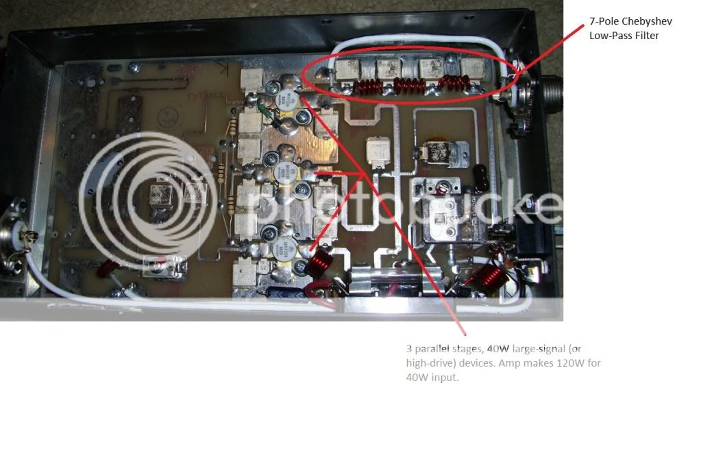
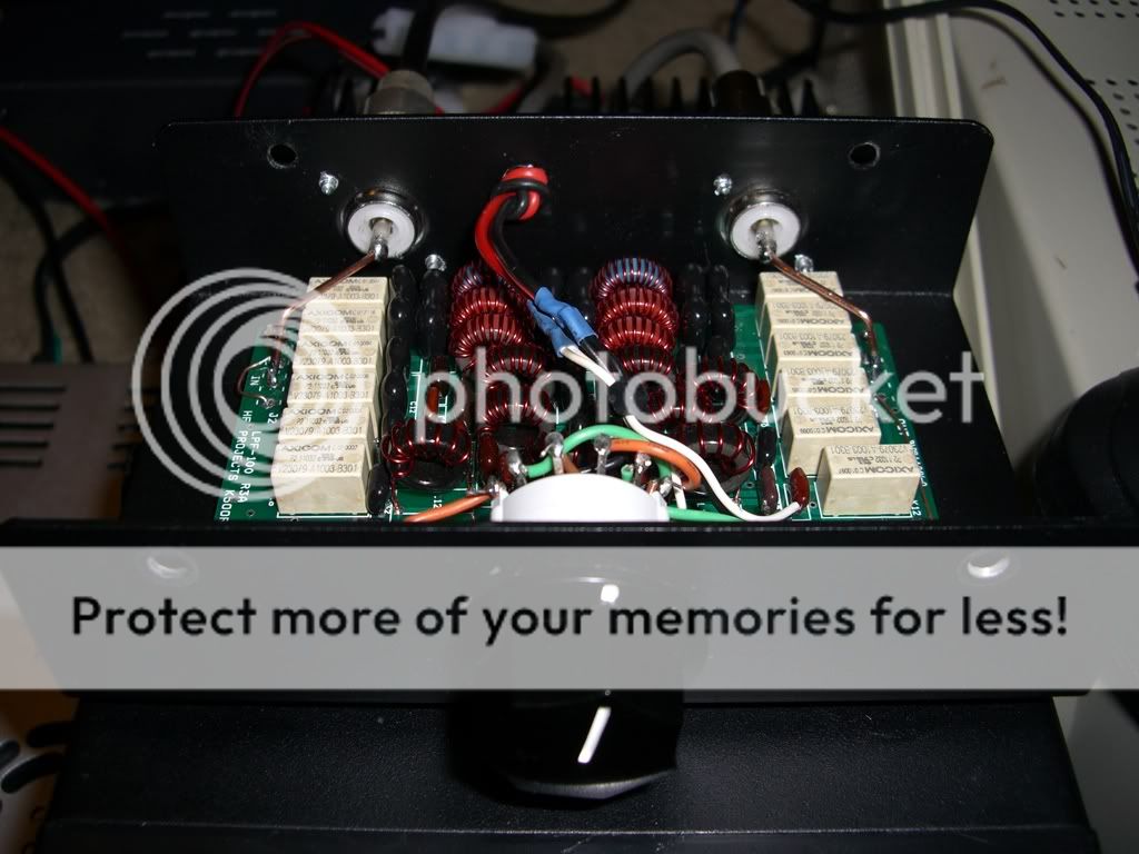
At VHF and UHF the wavelengths are short enough that a carefully shaped PCB trace acts as an inductor, so when that is combined with a capacitor or two we get a matching network suitable for use across a comparatively narrow bandwidth, usually about 10MHz wide at VHF and 20-30MHz wide at UHF. As can be seen in the top picture, there are 2 tuning capacitors, one at the amplifier input (just to the left of the row of transistors, and slightly towards the bottom of the pic) and output (right next to the relay). These allow the amplifier to be tuned to a specific 10MHz portion of it's full coverage range (136-174MHz). The amp will not cover this whole range at once though.
At VHF and UHF the wavelengths are short enough that a carefully shaped PCB trace acts as an inductor, so when that is combined with a capacitor or two we get a matching network suitable for use across a comparatively narrow bandwidth, usually about 10MHz wide at VHF and 20-30MHz wide at UHF. As can be seen in the top picture, there are 2 tuning capacitors, one at the amplifier input (just to the left of the row of transistors, and slightly towards the bottom of the pic) and output (right next to the relay). These allow the amplifier to be tuned to a specific 10MHz portion of it's full coverage range (136-174MHz). The amp will not cover this whole range at once though.

No expert here, but also think about this,
Think about Zin and Zout
Z in = Series Equivalent Input Impedance
Z out = Series Equivalent Output Impedance
If you are used to working with Toshiba 2sc2879 transistors
The Z in and Z out is very low, about 1.45 ohms, so you need a transformer to change the impedance to get closer to 50 ohms that we work with in most of our radio stuff.
The MRF 641( designed to work @ 470MHz) for example, has a built in matching network (yes) built into the transistor that makes it some what broad-banded, so you do not need to use wire wound transformers.
Same thing with the MRF 646 Transistor, it also has a internal input matching network.
Makes things much more simple when you do not need input/output transformers.
Good Stuff Eagle.
73
Jeff
Last edited:
LOL, I guess I am still stuck in old school with BJT`s, but I am learnin.
Thanks for the time you put into your posting here on the forum eagle, some really good stuff.
73
Jeff
Thanks for the time you put into your posting here on the forum eagle, some really good stuff.
73
Jeff
You know, this forum has given to me in that it counts as a major resource that I've used to learn. There are people here who know far more than I about this stuff, and often they've been kind enough to help me learn. Now I'm just trying to put information that I find fascinating out there so maybe someone else can benefit. It's no problem, believe me.
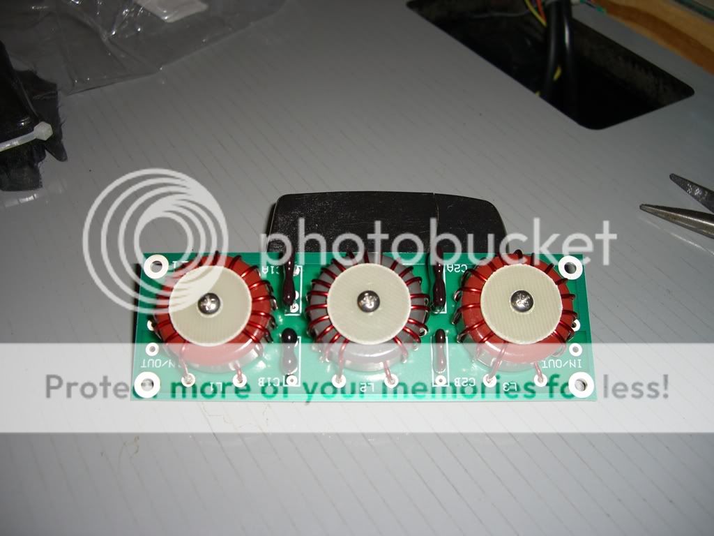
Just realized I had a couple amps here that show what we're discussing so I took a couple pics and labeled some key parts:
This is a 136-174 MHz class C FM-only commercial/public safety amplifier that is frequently found on the ham bands. It uses 3 single-ended stages:
Holy cow. Seems like a amp that takes 40 watts in to give 120 is terribly inefficient. Like... WHY BOTHER Inefficient. 40>120 is something like a 4.75 db increase, right. From what I understand you need to increase the signal 5db before it will even be noticable by the other person on the other end.
You do have a good point, but it's not quite so bad as to say "why bother". increasing the power output from 40 to 120W is still a noticeable increase. While math does help visualize what the difference will be, it doesn't always take the lay of the land and the antenna's height (or lack thereof) into consideration. Under adverse conditions or when the receiver is on the fringes of the transmitter's coverage area even a slight increase can mean the difference between contact and no contact.
Also, to add further, if you look at the picture you can see that there is a spot for another amplifier stage, with a cutout for the transistor clearly visible. In a slightly different model of this amplifier a drive stage is added to boost the gain. 5-15W in gives 120 out.
Holy cow. Seems like a amp that takes 40 watts in to give 120 is terribly inefficient. Like... WHY BOTHER Inefficient. 40>120 is something like a 4.75 db increase, right. From what I understand you need to increase the signal 5db before it will even be noticable by the other person on the other end.
The VHF and UHF amplifiers pictured above are designed around transistors manufactured in the 1980's. Older transistors used in these frequency ranges had much lower gains then typical HF transistors. Early solid state VHF marine radios often had 3 or more "pills" as they are called just to make 25 watts at 156 MHz. Now it's all done in a single RF power module that looks like an overgrown heatsink mounted IC. The design of VHF and UHF power transistors has advanced significantly since then and much higher gains in a single stage are possible now.
That's absolutely true. Some of today's MOSFET technology is simply incredible. It's possible today to obtain up to 1.25kW from 1.8-600MHz from a single device that costs about $250-300. Crazy stuff really when you think about how things were just a few years ago.
Hell, these here will do 1kW CW from 1.8-150MHz with adequate cooling (meaning copper heat-spreader and heatsink).. they are equivalent to a push-pull pair of "pills".
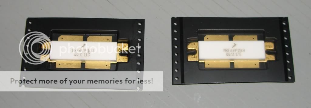
As a size reference the lines on the surface below them are 1/4" apart.
Hell, these here will do 1kW CW from 1.8-150MHz with adequate cooling (meaning copper heat-spreader and heatsink).. they are equivalent to a push-pull pair of "pills".
As a size reference the lines on the surface below them are 1/4" apart.
Here's a writeup I did a few weeks back detailing the construction of a low-pass filter kit for 80m. The same basic process applies to any HF/VHF band.
The complete kit for all 6 filters (160m-10m) can be purchased quite reasonably from Communication Concepts here. This is just in case anyone else wants to try their hand at building one of these kits.
It's absolutely worth browsing their other products. they have several amplifier kits to choose from, all are Motorola designs. The pricing of their kits isn't bad either..
Low-pass filters are an important part of a solid-state amplifier setup, either mounted inside the amp or built as an external band-selectable accessory. There is also generally a lot more info to be found on building amplifiers than building filters, especially in the CB world.
As discussed earlier in this thread, LPFs are important because they help remove unwanted harmonic junk from an amplified signal, which helps keep noise down across the radio spectrum. This helps all radio operators in obvious ways. They are also a component that's not often found in CB-type solid-state amplifiers (although some manufacturers include them), which is unfortunate since they aren't really very hard to design or build, especially with the software available today.
ELSIE filter design software and information for designing custom filters from scratch:
The filters I've used here are a kit, but for those interested in using software to design your own filters specific to your application, ELSIE works really well. It's simple, free and very easy to use. For most 2+ transistor RF amplifier applications, a simple 5 pole Chebyshev filter either with either a parallel capacitor at the input or a series inductor-input can be used. This information can be entered directly into Elsie, along with a Ripple Bandwidth of XXMhz (can be any number depending on the band to be used, for CB it would be 28), an Order (N)[7max] of 5 and an Input Term of 50 (for 50 ohm impedance to match the amplifier and transmission line). Bold words above are the actual functions in the ELSIE software, and you can see exactly where to enter them in the first screen of the program after you select "New Design" from the opening menu. Input the above figures and hit the "schematic" button at the top of the screen and BAM!, you've got a filter schematic ready to be built. To find what cores are best for your application, consult toroids.info. Once you've got a core picked out, you can usually just enter the part number on ebay and find them. You select toroid cores based on your frequency of operation and your power handling requirement. For the shorter wavelength bands (20m and up) air core coils can be made simply by winding heavy-gauge magnet wire around a cylindrical form. Owning an L/C (inductance/capacitance) meter is a must when hand-winding cores for a custom design, but they can be had fairly cheaply on ebay or Amazon.
Here's a little more info on building the filters:
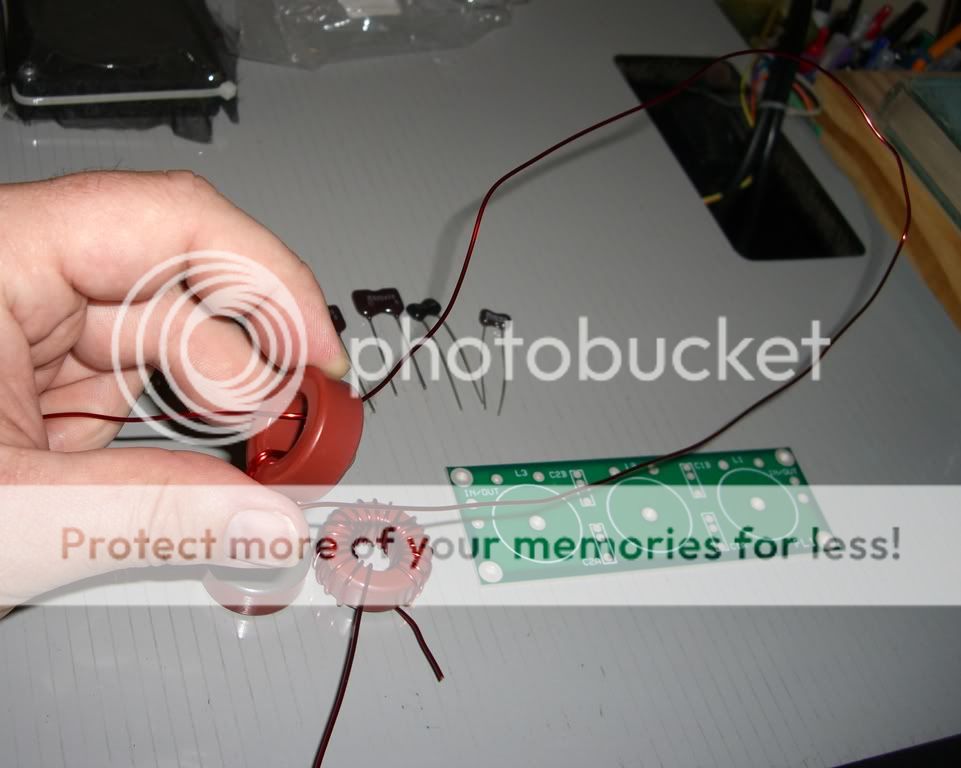
The toughest part about building the filters is winding the toroids.. particularly for the longer wavelength bands. I started with 160m since it involved the most turns of wire around the ferrite toroid core, namely 28 turns on the middle coil and 23 turns on the outer coils. The pics I've posted here were taken while building the 80m coil, which required 20 turns on the middle coil and 16 turns on the outer coils.
A helpful guide on how to wind toroids can be found here.
Basically It's just like you would think. You just pass the wire through the toroid core over and over, pressing the wire against the core with each turn so it's snug against it. Most coils are wound clockwise if it's not stated otherwise. To make sure you're winding clockwise, start by holding the toroid with the hole facing you. Take the wire and pass it through the hole from the back so that it passes through the hole towards you. Pull the wire through almost to the end, with a couple inches left over. Hold the wire tightly and wrap it down and around the core, passing again through the core to the right of the first pass. Holding the core so that the hole is facing you, then winding to the right after passing the wire through the core from the back ensures the the wire is wound in a clockwise direction. To verify this, you can compare the first few turns to the pictures here to see that the leads are on the same side of the coil.. these coils are all wound clockwise. A counter-clockwise coil will end up with the leads on opposite sides. The direction doesn't make a difference in the value of the coil, but it does ensure that your coils can all be mounted the exact same way. Once the coils are wound, you must strip the enamel insulation off the leads (I use an x-acto knife to scrape it off) and tin the leads with solder to ensure the best connection once it's soldered into a circuit. RF can be very senstive to bad connections.
Capacitors:
The capacitors are typically dipped silver-mica or ceramic disc, with silver-mica being preferred due to stability. The values provided by design software do not always match up to a manufactured capacitor, so often multiple capactors are used in parallel to achieve special values. Parallel capacitors add up directly in terms of value.
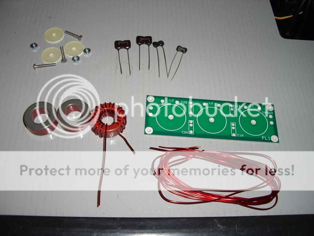
here's a few pics of the build process:
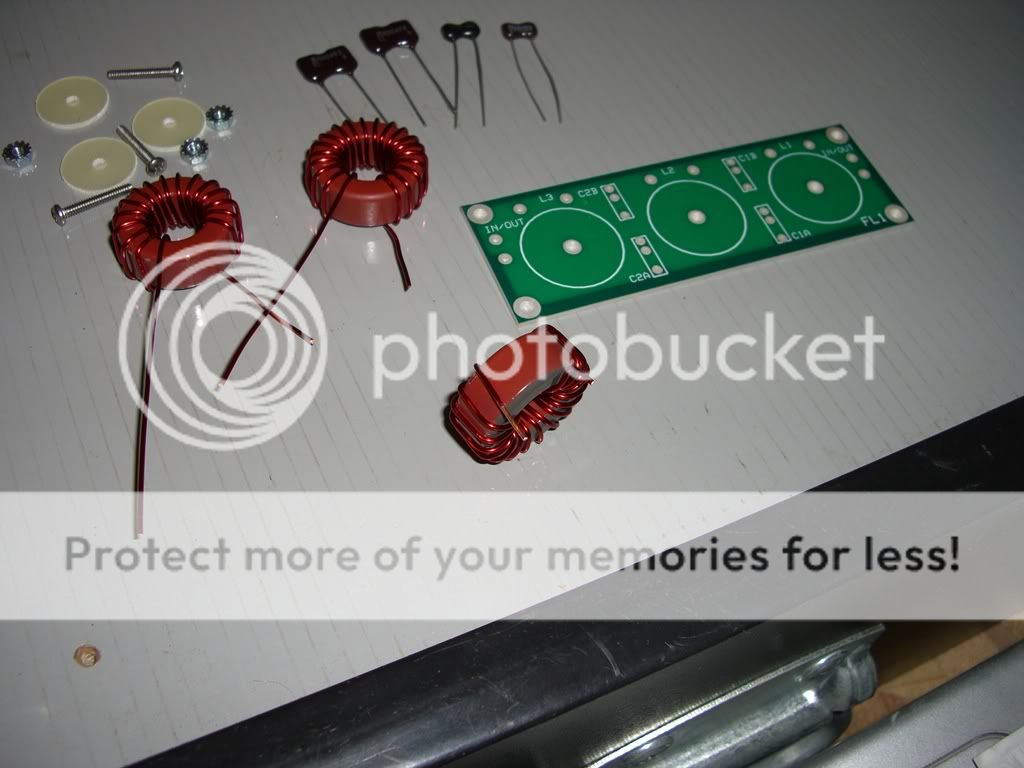
This shows all the parts for the 80m filter kit:
Winding the toroids:
Fully wound toroids (can be used as reference for clockwise windings):
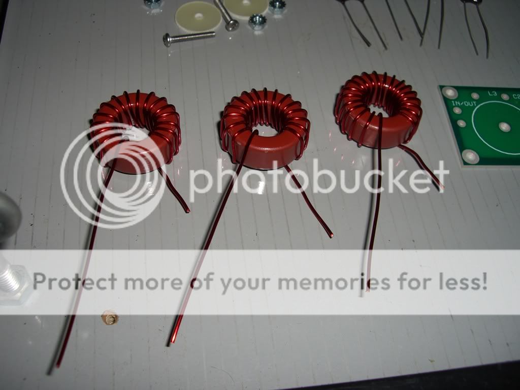
Toroid with leads cut and positioned to fit the PCB:
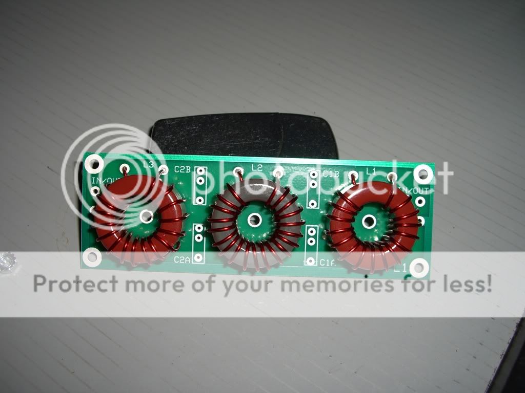
Toroids soldered in place:
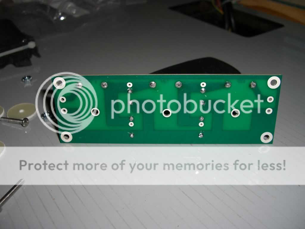
Back of board (to show circuit):
All Done!
Ultimately, to be able to filter across the entire HF band a set of filters will be required. Ideally the whole set should be either built into an amplifier or built into a free-standing band-switchable unit that can be used with any amp. Here's a small, lower-powered filter kit (available here) I built that is a good example of what I'm describing:
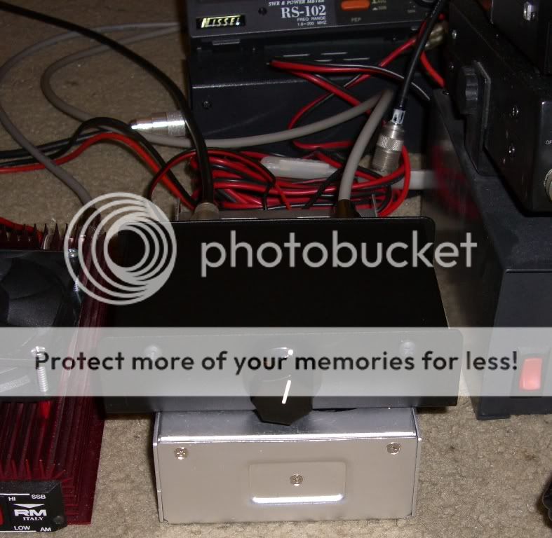
This contains 6 filters that together span from 1.8-30MHz. It'll handle up to 100W PEP.
I needed something that will handle more power, so that's why I turned to the Communication Concepts (CCI) filters described above. They are rated to 300W PEP, but can handle up to 500-600W PEP.
For these higher-powered filters I decided that this design will work the best and be the most practical for combining the 6 filters into a single band-selectable device:
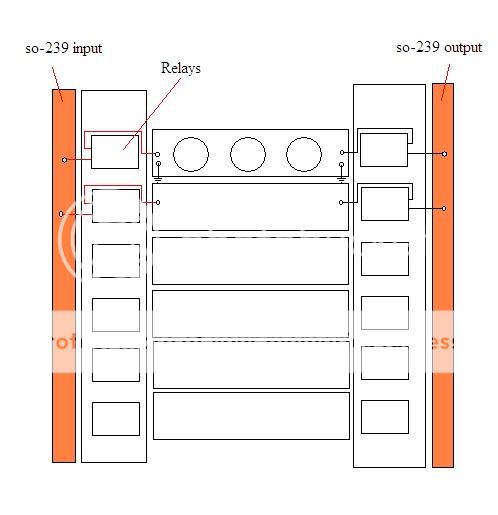
Each band can be selected via a 6-position switch that provides power to each set of relays.
The finished project is not complete yet, so I'll post more pics when I finally get it done.
The complete kit for all 6 filters (160m-10m) can be purchased quite reasonably from Communication Concepts here. This is just in case anyone else wants to try their hand at building one of these kits.
It's absolutely worth browsing their other products. they have several amplifier kits to choose from, all are Motorola designs. The pricing of their kits isn't bad either..
Low-pass filters are an important part of a solid-state amplifier setup, either mounted inside the amp or built as an external band-selectable accessory. There is also generally a lot more info to be found on building amplifiers than building filters, especially in the CB world.
As discussed earlier in this thread, LPFs are important because they help remove unwanted harmonic junk from an amplified signal, which helps keep noise down across the radio spectrum. This helps all radio operators in obvious ways. They are also a component that's not often found in CB-type solid-state amplifiers (although some manufacturers include them), which is unfortunate since they aren't really very hard to design or build, especially with the software available today.
ELSIE filter design software and information for designing custom filters from scratch:
The filters I've used here are a kit, but for those interested in using software to design your own filters specific to your application, ELSIE works really well. It's simple, free and very easy to use. For most 2+ transistor RF amplifier applications, a simple 5 pole Chebyshev filter either with either a parallel capacitor at the input or a series inductor-input can be used. This information can be entered directly into Elsie, along with a Ripple Bandwidth of XXMhz (can be any number depending on the band to be used, for CB it would be 28), an Order (N)[7max] of 5 and an Input Term of 50 (for 50 ohm impedance to match the amplifier and transmission line). Bold words above are the actual functions in the ELSIE software, and you can see exactly where to enter them in the first screen of the program after you select "New Design" from the opening menu. Input the above figures and hit the "schematic" button at the top of the screen and BAM!, you've got a filter schematic ready to be built. To find what cores are best for your application, consult toroids.info. Once you've got a core picked out, you can usually just enter the part number on ebay and find them. You select toroid cores based on your frequency of operation and your power handling requirement. For the shorter wavelength bands (20m and up) air core coils can be made simply by winding heavy-gauge magnet wire around a cylindrical form. Owning an L/C (inductance/capacitance) meter is a must when hand-winding cores for a custom design, but they can be had fairly cheaply on ebay or Amazon.
Here's a little more info on building the filters:
The toughest part about building the filters is winding the toroids.. particularly for the longer wavelength bands. I started with 160m since it involved the most turns of wire around the ferrite toroid core, namely 28 turns on the middle coil and 23 turns on the outer coils. The pics I've posted here were taken while building the 80m coil, which required 20 turns on the middle coil and 16 turns on the outer coils.
A helpful guide on how to wind toroids can be found here.
Basically It's just like you would think. You just pass the wire through the toroid core over and over, pressing the wire against the core with each turn so it's snug against it. Most coils are wound clockwise if it's not stated otherwise. To make sure you're winding clockwise, start by holding the toroid with the hole facing you. Take the wire and pass it through the hole from the back so that it passes through the hole towards you. Pull the wire through almost to the end, with a couple inches left over. Hold the wire tightly and wrap it down and around the core, passing again through the core to the right of the first pass. Holding the core so that the hole is facing you, then winding to the right after passing the wire through the core from the back ensures the the wire is wound in a clockwise direction. To verify this, you can compare the first few turns to the pictures here to see that the leads are on the same side of the coil.. these coils are all wound clockwise. A counter-clockwise coil will end up with the leads on opposite sides. The direction doesn't make a difference in the value of the coil, but it does ensure that your coils can all be mounted the exact same way. Once the coils are wound, you must strip the enamel insulation off the leads (I use an x-acto knife to scrape it off) and tin the leads with solder to ensure the best connection once it's soldered into a circuit. RF can be very senstive to bad connections.
Capacitors:
The capacitors are typically dipped silver-mica or ceramic disc, with silver-mica being preferred due to stability. The values provided by design software do not always match up to a manufactured capacitor, so often multiple capactors are used in parallel to achieve special values. Parallel capacitors add up directly in terms of value.
here's a few pics of the build process:
This shows all the parts for the 80m filter kit:
Winding the toroids:
Fully wound toroids (can be used as reference for clockwise windings):
Toroid with leads cut and positioned to fit the PCB:
Toroids soldered in place:
Back of board (to show circuit):
All Done!
Ultimately, to be able to filter across the entire HF band a set of filters will be required. Ideally the whole set should be either built into an amplifier or built into a free-standing band-switchable unit that can be used with any amp. Here's a small, lower-powered filter kit (available here) I built that is a good example of what I'm describing:
This contains 6 filters that together span from 1.8-30MHz. It'll handle up to 100W PEP.
I needed something that will handle more power, so that's why I turned to the Communication Concepts (CCI) filters described above. They are rated to 300W PEP, but can handle up to 500-600W PEP.
For these higher-powered filters I decided that this design will work the best and be the most practical for combining the 6 filters into a single band-selectable device:
Each band can be selected via a 6-position switch that provides power to each set of relays.
The finished project is not complete yet, so I'll post more pics when I finally get it done.
Last edited:
To add to the above post, I had an interesting experience and discovered a major improvement while building this set of low-pass filters from CCI. Some of the following plots and circuits were posted in the OP, but they are most relevant here.
In the base configuration (5-pole) the input impedance varied a good amount over the bands that the filter will be used on, resulting in a highly variable input SWR. Here I'll be discussing the 10m filter since it's been the main subject of my experimentation. The input SWR of the 10m filter as constructed in accordance with the supplied instructions was perfectly usable from 28.0MHz to 29.3MHz, but the power handling capability needed to be derated at the bandwidth edges as the input SWR approached 1.8:1, indicating an impedance mismatch which seemed to overheat one of the capacitors (in the photo below it's the lower right-hand mica cap in the central group of 4) to the point of burning out. In it's original configuration the maximum continuous (100% duty for 10+ minutes) power I could pass through the filter was around 75W without eventual damage. These filters are rated to 300W PEP, which is actually conservative since the toroids and capacitors should allow up to 500W PEP if optimized properly, so by my logic they should be able to handle at least 120W continuously. I felt that there was some need for improvement, so I modeled the circuit in ELSIE so that I could play around with various configurations and view their responses and parameters.
Here's a graph of the cutoff (red) and vswr (blue) of the 10m filter as supplied by CCI (based on a schematic from an ARRL text). The plot is graduated in MHz along the bottom, VSWR on the left and Transmission in dB on the right:

The swr curve has some nice low points that kind of roughly correspond to the bands that the filter will be used on (10/12m) but they also peak above 2.0 at certain points across the bandwidth. In real-world usage these peaks fall closer to the bands of operation than I'd like, resulting in somewhat high SWR at the edges of these bands. As I'm looking for peak performance across the widest possible bandwidth I felt improvement was possible and necessary.
A primary interest of mine was to keep the core configuration of the filter intact, so I didn't want to alter the cap values or the inductor values of the original configuration. That left the option of adding more components.. by adding 2 more capacitors I ultimately ended up with a 7-pole filter with much better input impedance values and sharper cutoff.. both good things! Plus the finished mod was about as easy as it gets.
As can be seen in the original schematic the main capacitance consists of 118pF shunted to ground. This is comprised of a 100pF cap in parallel with an 18pF cap on the board itself:

I found that adding two more capacitors with values roughly half of the originally installed capacitance (118/2, or ~68pF in this case since I had quite a few 68pF caps on hand) at the input and output of the filter resulted in better performance across the bandwidth with much less loss, resulting in full power-handling capability (easily handles 120W+ continuous without major heating):

Here's the curves for the improved 7-pole filter. You can see that the input vswr no longer peaks nearly as high near the intended bands of operation (area between 20MHz and 30MHz) while the cutoff is sharper. The real-world performance mimicked the software plots almost exactly:

Here's the finished filter. The added caps are simply soldered across the input and output connection points:
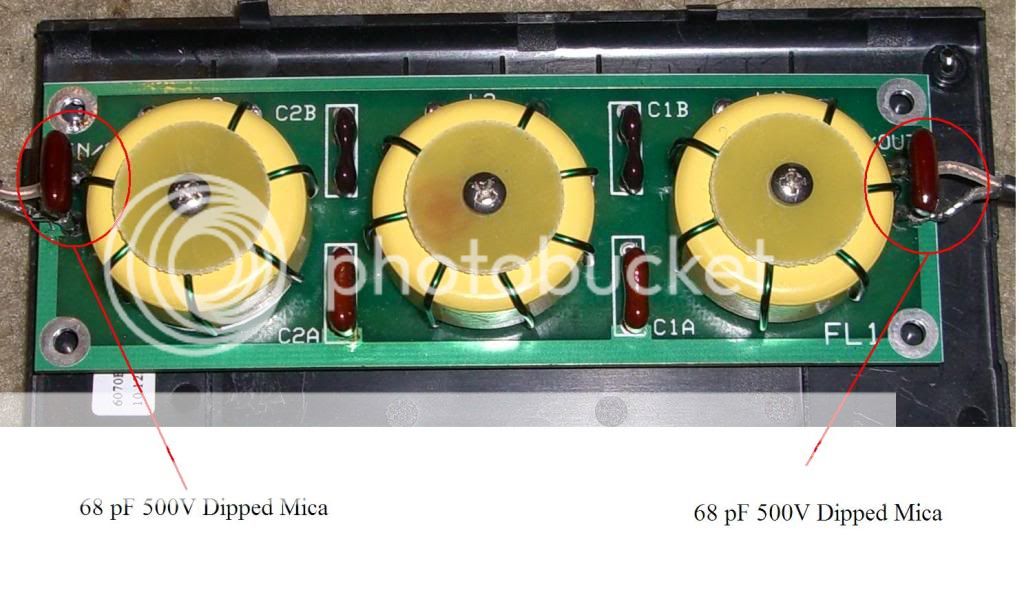
This logic can be applied to all of the filters. I found that adding 2 more capacitance poles with values of roughly half of the originally installed capacitance values made for a much more user-friendly and better performing filter regardless of the intended band of operation.
In the base configuration (5-pole) the input impedance varied a good amount over the bands that the filter will be used on, resulting in a highly variable input SWR. Here I'll be discussing the 10m filter since it's been the main subject of my experimentation. The input SWR of the 10m filter as constructed in accordance with the supplied instructions was perfectly usable from 28.0MHz to 29.3MHz, but the power handling capability needed to be derated at the bandwidth edges as the input SWR approached 1.8:1, indicating an impedance mismatch which seemed to overheat one of the capacitors (in the photo below it's the lower right-hand mica cap in the central group of 4) to the point of burning out. In it's original configuration the maximum continuous (100% duty for 10+ minutes) power I could pass through the filter was around 75W without eventual damage. These filters are rated to 300W PEP, which is actually conservative since the toroids and capacitors should allow up to 500W PEP if optimized properly, so by my logic they should be able to handle at least 120W continuously. I felt that there was some need for improvement, so I modeled the circuit in ELSIE so that I could play around with various configurations and view their responses and parameters.
Here's a graph of the cutoff (red) and vswr (blue) of the 10m filter as supplied by CCI (based on a schematic from an ARRL text). The plot is graduated in MHz along the bottom, VSWR on the left and Transmission in dB on the right:
The swr curve has some nice low points that kind of roughly correspond to the bands that the filter will be used on (10/12m) but they also peak above 2.0 at certain points across the bandwidth. In real-world usage these peaks fall closer to the bands of operation than I'd like, resulting in somewhat high SWR at the edges of these bands. As I'm looking for peak performance across the widest possible bandwidth I felt improvement was possible and necessary.
A primary interest of mine was to keep the core configuration of the filter intact, so I didn't want to alter the cap values or the inductor values of the original configuration. That left the option of adding more components.. by adding 2 more capacitors I ultimately ended up with a 7-pole filter with much better input impedance values and sharper cutoff.. both good things! Plus the finished mod was about as easy as it gets.
As can be seen in the original schematic the main capacitance consists of 118pF shunted to ground. This is comprised of a 100pF cap in parallel with an 18pF cap on the board itself:
I found that adding two more capacitors with values roughly half of the originally installed capacitance (118/2, or ~68pF in this case since I had quite a few 68pF caps on hand) at the input and output of the filter resulted in better performance across the bandwidth with much less loss, resulting in full power-handling capability (easily handles 120W+ continuous without major heating):
Here's the curves for the improved 7-pole filter. You can see that the input vswr no longer peaks nearly as high near the intended bands of operation (area between 20MHz and 30MHz) while the cutoff is sharper. The real-world performance mimicked the software plots almost exactly:
Here's the finished filter. The added caps are simply soldered across the input and output connection points:
This logic can be applied to all of the filters. I found that adding 2 more capacitance poles with values of roughly half of the originally installed capacitance values made for a much more user-friendly and better performing filter regardless of the intended band of operation.
ok, can someone tell me what all that extra stuff packed in a ham amp is, that isn't in the amp section. i've conversed with builders on facebook, youtube and at places like this one. i've gotten many unclear answers. some say it's filters, some say it's like input tuning for each band, and i'm still not getting a clear picture. i know the transformers in the amp section are wide banded. i know my mfj swr analyzer's out put is in milliwatts. so i manually keyed the amp by hot wiring the keying transistor. i was told swr analyzer's not enough power to cause a swr reflect signal. but when i took it to 160meters it began showing a reflected signal. so i feel that some power could be applied to produce some sort of usable signal in a band other than 10 and 11 meters. and the box i'm talking about is a texas star 250 with Toshiba's 2sc2099's. it is said to be an ab class amp. it does talk ssb well.
i'm sure, if you feed any amp with a dirty radio. you'll get dirty back out.
now this is why i jumped into this. i have a known c class 16 transistor amp, i want to convert to ab class. but have it switchable to c class to run on 10 meters fm and fm for contacts in england. as fm doesn't put out the same type of modulation that causes near the harmonics as am or ssb would. buy over modulating a given modulated signal.
dxChat
- No one is chatting at the moment.