Backing story: About 10 years ago at a garage sale at the end of my block... I bought a Wilson 1000 Mag Mount for $10. I have tried to set it before with just an SWR meter and it always seemed tricky... like it didn't want to behave. When I first got it... the coax was pretty ragged. So I dismantled the thing, removed the RG/58 and soldered in a nice length of RG/8X. No shorts in my coax job (long pants only!!!). Buttoned it all up.
Fast forward to tonight.....
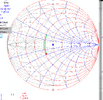
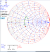
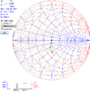
I am out there with this W 1000 and an MFJ antenna analyzer. No matter WHAT I DO.... the center is up in the upper 28 Mhz to 29 Mhz area...
So.... the whip is too short .... right? Well this one is bottomed out!!!!!!!! And still it is tuning WAY up there....
So I wonder if somebody sawed off the whip???
Visually.. it doesn't look like it. So I look up the specs. Every ad that I see says that the whip should be 62". So excuuuuuuuuuse me while I whip out my tape measure. MINE measures about 65"..... WHAT???? Did the previous owner swap the right one out with a longer one????
But....wait...... this things is resonant in the 29 Mhz area..... a long whip WOULD NOT add up to an antenna resonating too high!!!!!
So I am sitting here thinking..........about ALL the WARS I have seen over COAX LENGTH.........
Would my replacing the original RG/58 coax with a random length of RG/8X be causing this thing to tune high like that???? To ME it sounds ridiculous... but I just can't come up with anything else.
IN a fit of goofiness.... I got a cliplead/copper wire extension....about 4" long...and clipped it on to the tip of the whip.It DID move it down...but ONLY to about 28.3 Mhz with the stinger bottomed out.
At that point.... I quit....before I got to thinking about selling every piece of radio gear I own. I put my toys away, came in here.... to lie down on the "psychologist's couch" so to speak........
Has anyone else had this kind of nonsense go on? The whip is 2" - 3" longer than it should be.... I ADD 4" to it..... and it STILL won't come down under 28.3 Mhz? Did the coax I put on do that?????
I need a drink..........


