There is decent information on that PLL here:
Pin 4 is not a simple 5kc jump. It doesn't work like that. When you bring that pin low, the 10.24MHz reference is divided by 2048 instead of 1024. This sends 5kc to the phase detector instead of 10kc. On the surface, it may seem that this would shift the output by 5kc, but it doesn't, it shifts it by 5kc*N.
SSB radios have clarifiers and you might be better off attacking it there and hoping there is enough pulling range. I have not yet looked at any of the radio schematics you listed, but if we look at this PLL02A diagram from the internet, we can see how screwed we would be if this was the circuit we had to work with.
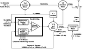
Lets say you ground pin 4 and have 5kc at the phase detector. To have the same VCO frequency, we would need an N value of 660 for ch1. Unfortunately, we only have 9 binary inputs and 2^9=512.
If you were to leave it at 10kc and pull the 10.695MHz crystal by 5kc (may be tricky), it would only affect TX and do nothing for RX. That's useless too.
If you were to pull the 10.24MHz crystal, setting aside the PLL error it will introduce, this too is a terrible mod because TX uses the doubled signal only whereas RX uses both the doubled signal and the fundamental in two separate mixers. The pulling would have to be different for RX and TX.
I am not saying it is impossible, but one thing I can tell you is that for 5kc steps on the binary inputs, you need a top end loop mix output below 5kc * (2^9 -1), or 2.555MHz, to not run out of N values. Such a mod would likely have the channel dial moved over to the 8 most significant bits and a toggle on the least significant bit to operate the 5kc jump. Or something like that.
I better go to bed, my lungs need a break lol.



