The RCI-made base radios with built-in amplifiers like the RCI2990, Eagle 5000, Galaxy Saturn Turbo, or the General Stonewall Jackson are shipped with the amplifier always active.
The radio's owner will sooner or later wish to run the radio "barefoot", with the amplifier on standby.
When asked, I reply "so you want the suicide switch installed?"
The name suggests right away that sooner or later some 'barefoot only' accessory will be installed in the coax line downstream from the radio, and that switch will get flipped the wrong way before keying the mike.
And then, "poof". Murphy's Law.
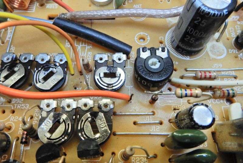
Another drawback is the way the radio's maximum carrier is set. In the Stonewall, the trimpot that does this is marked "VR13". If you set VR13 for a max carrier of 30 Watts with the amplifier on, the max carrier you can get barefoot will be around one Watt, plus or minus.
Joe base station will want more barefoot carrier than that. If you set VR13 for a 3-Watt carrier with the suicide switch 'off' you'll get more than a hundred Watt carrier with the amplifier activated.
Not safe. Only borderline suicidal.
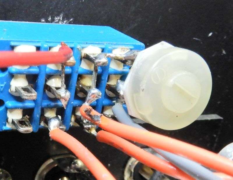
The solution we have worked out requires a switch with three sections. One to shut down the keying circuit in the linear. One to add a new trimpot to the carrier-set circuit and one more to light a LED nestled inside the headphone jack. The LED will be on whenever the suicide switch is in the "high" position. At least it's a reminder not to key the mike until your barefoot-only accessory is unhooked from the coax.
Yeah, I know, it's a four-section switch. Didn't have any 3PDT on hand that day, only two and four-circuit switches. Just ignore the unused section. That's what the radio does.
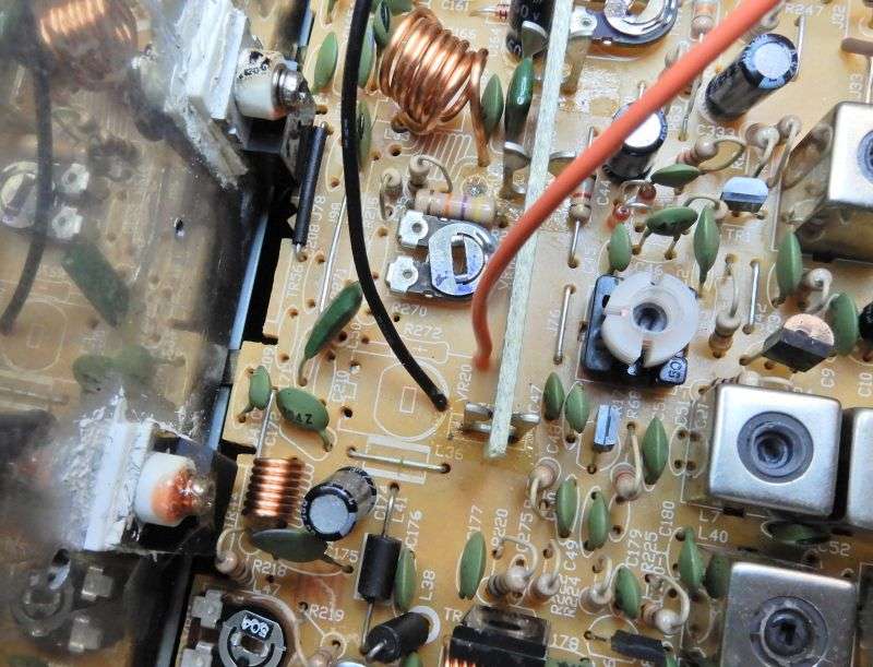
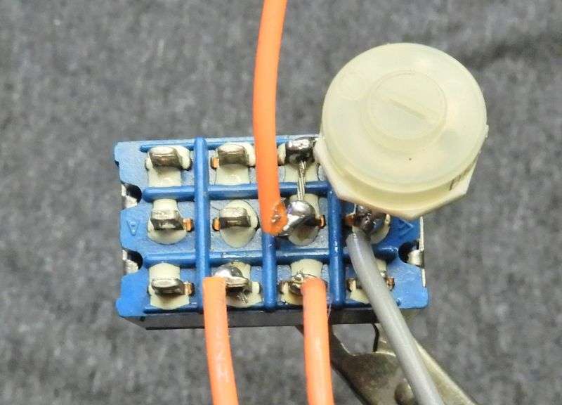
First the red wire that keys the amplifier gets unsoldered from this hole in the main pcb just forward of the final transistor. In this radio, an orange wire gets added to this hole, long enough to reach the barefoot switch.
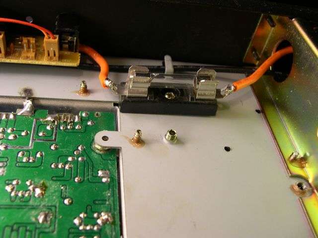
This pic shows the whole shebang installed. Didn't shoot one that shows just the amplifier-keying circuit alone. The left-most two wires handle this.
Next the forward-facing end of R237 gets pulled out of the pc board. R237 feeds 9 Volts DC to VR13. The hole we pulled it out of supplies the 9 Volts. A wire is lap-soldered to the free end of R237, and a sleeve slid over to insulate the bare lap-soldered end. This is the gray wire seen on the back of the switch. Another wire goes into the hole where R237 had been connected. Both wires should reach to the barefoot switch easily. This wire will feed through the switch to R237 and the LED on the front panel.
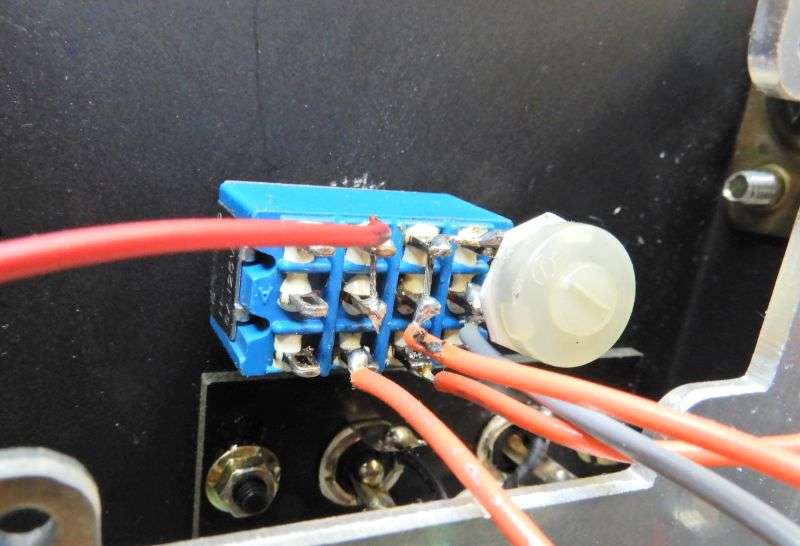
The new 5k trimpot mounted on the switch gets shorted across it's two connected pins when the switch is down, for barefoot side. When the switch is flipped up for high side, the new trimpot is in series with R237, and allows you to adjust the carrier with the amplifier active, separate from the 'barefoot' setting you chose using VR13.
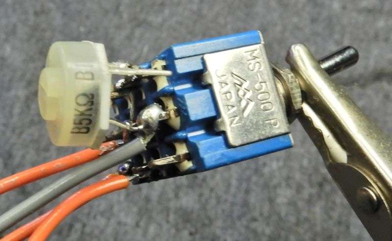
This detail shows that the orange wire coming from the hole where R237 was soldered is feeding two sections of the switch. The top pin of the new trimpot, and the switch section to its left. The remaining unidentified orange wire leads away to the hot side of that red LED in the headphone jack. I'll leave the dirty business of threading the LED's wires into the headphone jack and out the rear end. The LED's black wire gets grounded to the pc board. Almost doesn't matter where, so long as you DON'T try grounding it to the metal chassis. Won't work.
Now you can set VR13 for 3 or 4 Watts, whatever the owner wants. The trimpot on the back of the switch will allow you to set high side max carrier to a safe level.
Hopefully I didn't scramble the order of the pics and the text. It's bedtime.
If It's scrambled I'll fix it next chance I get.
Oh, and one last note. This trick doesn't seem to work properly on the radios with the surface-mount main circuit boards. Only seems to work right on the older boards with the through-hole construction. Never have found out why.
73
The radio's owner will sooner or later wish to run the radio "barefoot", with the amplifier on standby.
When asked, I reply "so you want the suicide switch installed?"
The name suggests right away that sooner or later some 'barefoot only' accessory will be installed in the coax line downstream from the radio, and that switch will get flipped the wrong way before keying the mike.
And then, "poof". Murphy's Law.
Another drawback is the way the radio's maximum carrier is set. In the Stonewall, the trimpot that does this is marked "VR13". If you set VR13 for a max carrier of 30 Watts with the amplifier on, the max carrier you can get barefoot will be around one Watt, plus or minus.
Joe base station will want more barefoot carrier than that. If you set VR13 for a 3-Watt carrier with the suicide switch 'off' you'll get more than a hundred Watt carrier with the amplifier activated.
Not safe. Only borderline suicidal.
The solution we have worked out requires a switch with three sections. One to shut down the keying circuit in the linear. One to add a new trimpot to the carrier-set circuit and one more to light a LED nestled inside the headphone jack. The LED will be on whenever the suicide switch is in the "high" position. At least it's a reminder not to key the mike until your barefoot-only accessory is unhooked from the coax.
Yeah, I know, it's a four-section switch. Didn't have any 3PDT on hand that day, only two and four-circuit switches. Just ignore the unused section. That's what the radio does.
First the red wire that keys the amplifier gets unsoldered from this hole in the main pcb just forward of the final transistor. In this radio, an orange wire gets added to this hole, long enough to reach the barefoot switch.
This pic shows the whole shebang installed. Didn't shoot one that shows just the amplifier-keying circuit alone. The left-most two wires handle this.
Next the forward-facing end of R237 gets pulled out of the pc board. R237 feeds 9 Volts DC to VR13. The hole we pulled it out of supplies the 9 Volts. A wire is lap-soldered to the free end of R237, and a sleeve slid over to insulate the bare lap-soldered end. This is the gray wire seen on the back of the switch. Another wire goes into the hole where R237 had been connected. Both wires should reach to the barefoot switch easily. This wire will feed through the switch to R237 and the LED on the front panel.
The new 5k trimpot mounted on the switch gets shorted across it's two connected pins when the switch is down, for barefoot side. When the switch is flipped up for high side, the new trimpot is in series with R237, and allows you to adjust the carrier with the amplifier active, separate from the 'barefoot' setting you chose using VR13.
This detail shows that the orange wire coming from the hole where R237 was soldered is feeding two sections of the switch. The top pin of the new trimpot, and the switch section to its left. The remaining unidentified orange wire leads away to the hot side of that red LED in the headphone jack. I'll leave the dirty business of threading the LED's wires into the headphone jack and out the rear end. The LED's black wire gets grounded to the pc board. Almost doesn't matter where, so long as you DON'T try grounding it to the metal chassis. Won't work.
Now you can set VR13 for 3 or 4 Watts, whatever the owner wants. The trimpot on the back of the switch will allow you to set high side max carrier to a safe level.
Hopefully I didn't scramble the order of the pics and the text. It's bedtime.
If It's scrambled I'll fix it next chance I get.
Oh, and one last note. This trick doesn't seem to work properly on the radios with the surface-mount main circuit boards. Only seems to work right on the older boards with the through-hole construction. Never have found out why.
73
Last edited: