• You can now help support WorldwideDX when you shop on Amazon at no additional cost to you! Simply follow this Shop on Amazon link first and a portion of any purchase is sent to WorldwideDX to help with site costs.

Super jopix 1000 no tx problem

NODENS

Member
Aug 2, 2018
50
7
18
Good afternoon, I have a super jopix 1000 (almost equal to ss3900) with the following problem.
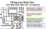
The radio receives perfect in all bands, but no tx on any band. The led turn off from green when I try to transmit. Switching transistor (tr38) is OK when switching the micro to transmit. Voltage on tr51 collector is 0, and in tr 49 0 aswelk. I'm despite because led no switching to red. Which is the relation between both scenarios?. Any idea what can I try to see?

Thx very much
 

Red led don't turn on when switching to tx. Transistor tr38 is OK and offering the 8v in the collector when pushing micro. I suppose something is taking the 8v to ground in the path to led, not sure what. And regulators tr51, tr50, tr49 not have the proper voltage either. Voltage in tr51 collector is 0 when transmitting. I'm not sure the existing relation between led not turning red and those transistors that comes after IC4
 
Ok, you say it's a lot like SS3900 - try this link to see if anything matches up...

http://www.cbtricks.com/radios/rci/index.htm

A ton of radios - so it's in the hope that you'd find something that would be useable - including a SS3900 - some stuff in there...

It looks like your REGULATOR is ok, you have 8V DC for RX and general...but you TX SWTICHNIG is not working.
 

Attachments

  • 4558Chip.png
    4558Chip.png
    154.5 KB · Views: 14
The chasis and components is a ss3900 yes. I will try to look what is dropping the 8v from tx switch transistor to ground and I will write it here if can help someone in the future. Its clear something drops the existing tx voltage to ground in the path from switching tx transistor (tr38 in schema) to led. The reason why tr51, 49 and 50 does not have their voltages must be related the switching is being drop to ground in some place I suppose.
 
Hi, an update:
Tx Led is not geting on because is dead that led, but tx switching is ok in tr38.

Now i can center my efforts in modulators (real broken part i think). All modulators transistors has wrong votages on collectors and emiiter or base not sure. For example in TR51 (2sa1012), i can find only 13,5 volts in one leg, 0 in rest of them. The same with tr50, and tr49.

I have changed them but same result. I think that i could start tracing from tr40,41 regulators where is supoused to generate the 8 volts line for modulators and so, until i arrive to vr13 and modulating transistors.

Am i taking the wrong path or do you think it is a good point to start tracing the missing vottages in modulators?

I have not too much experience on this kind of equipments, but i enjoying with this equipment trying to learn how it works.

Thx very much
 
Last edited:
Well, it will take some more time - did you find a schematic we all can work with? OR at least a pic of the board you're using?

Why?

The 4558 Chip uses one side for Audio - the other side is for RX and TX switch - and it uses that 2nd half as a "AND" gate. (Inverts it's output from Low to HIGH)

IF PLL is in lock, and TX is enabled on Pin 3 of the Microphone - I turn on - sort of thing.

So with your AM regulator section being "dead" - indicates you may have a dead line for various reasons - catastrophic failure - trace opened like a fuse, broken part or jumper or your TX Transistor failed. . The AM Regulator - or the line that goes to the Collectors of the Driver and Final - is on all the time. You can test for that if you have a trimpot that says AM POWER or CARRIER POWER - something to that effect - silkscreened on the PCB. (But that is if your radio is similar to the SS3900 in board type not just size or looks - board type refers to the maker - like Galaxy or Cybernet - they found something that worked and used it throughout their radio line as a means to keep costs and repairs down - familiarity with the models - like layers - easier to fix.

There is the TX switch - which turns on the Red LED - that section usually gets a BIAS voltage from the TX power swtich.

But I can only offer advice up to that point - because on many radios like the SS3900 they use a Mirror board, a jumper - that shorts across 3 pins - one comes from the AM regulator, which sends power to the other two - one to the Driver and One to the Final.

This is why I'd like to have a visual of your problem - then it's easier to walk you thru it.
 
This schema adjust to this radio 100%. I tested. Removing tp7, 8,9 jumper to measure tr50, 51,49 and yet 0 volts on collectors. Collector and emitter in tr51 remains in 0 volts for example.

I thought I could start tracing 8 volts from tr40-41 regulators to vr13 and from there to tr 49 base that is zero volts too. Vr13 was zero in both sides, that's the reason I was thinking to start going back from there to regulators and then I will worry about where is the around 13 volts that should exist in tr51 emitter too.

Do you think is a good approach or maybe should I start in another point?

Thx
 

Attachments

  • superstar_3900.gif
    superstar_3900.gif
    277.1 KB · Views: 12
Ok, TP 7, 8 and 9 have to short together in order for TP 9 TO SEND POWER to the Collectors connected thru TP 8 and TP 7.

So, what I see to help identify...

TP 9 from the AM Regulator - TR51

TP 8 GOES TO Driver TR44

TP 7 GOES TO Final TR43

So for now, we measure FROM TP to Board Ground (Tank coil can shield is good to use)

Whats TP 9 to Ground VOLTAGE?
 
Tp7 has 0 volts, tp8 and tp9 0. I was trying to go to previous phase analysing as tr 51 has 0 volts in collector too, trying to see the point from which 5,60 volts in tr51 and 50 should come and the absent 13volts in tr51 emmiter
 
Ok, TR51 may be bad. Hold this for now...

Your you should - see 5~6 Volts on TP 9 FROM TR51.

You do not, so we proceed - TR 51 suspect

AMP Test Point - by VR 13 - any VOLTAGE?

Other Symptoms are

No RED TX light

Check for

Any GREEN RX light?
 
Hi, I update with new discovers :
R237(in serie with vr13 was blown or Removed. I put its Resistor and now I have 8 volts in vr13, and from vr13 it's drops To 3v through r238 and r239 to tr49 base (should be around 6v no 3). Where is the Other 3v?????
The 2 resistors are OK both 5k6. Is there another amount of volts incoming from another path to sum in vr13???. This is my first doubt.

Another thing is that tr51 base has only around 2.60 volts, not around 12.50. I have missing volts in modulators transistors. All test was done with tp7, 8,9 removed as I know another problem exist in final transistor area with a short circuit. But I will deal that later. I want to estabilize required voltages on tr49, 5,,51,52...

Any ideas?
 
Last edited:
Good job!

Let's see about that AMP voltage - that is your power from 8V constant - so there is a 100 ohm (R237) to buffer it and the R238 is 5.6K and R239 is also 5,6K GOOD!

Continue - Audio is taken in at C191 so you need some working resistance there to allow C191 to send a charge across into TR49.

TR 49 SAMPLES from Output of TR 51 Main AM Regulator power switch - uses R240 as 560 ohms, and R241 is supposed to be 15 ohms. There is a cap that if it went shorted (Failed) it may affect your voltages - C190 - its an Electrolytic 100uF - should be replaced with a 50V unit...same value...
 
Thx mate for the info, you are right the path in r240, 241 was what I missed, I'm new in this technology hehe, I will check tomorrow that and that capacitor could be the key maybe. I will back tomorrow with new feedback, Thx a lot for your support.
 
Good morning, another doubt I have. Later I will check previous answer when at home. How 12.5 volts in tr51 base is achieved? It is. Another voltage is under the specification, but I can't see in schema how 12.5 volts can be generated...
 

dxChat
Help Users
  • No one is chatting at the moment.
  • @ Wildcat27:
    Hello I have a old school 2950 receives great on all modes and transmits great on AM but no transmit on SSB. Does anyone have any idea?
  • @ ButtFuzz:
    Good evening from Sunny Salem! What’s shaking?
  • dxBot:
    63Sprint has left the room.
  • dxBot:
    kennyjames 0151 has left the room.