There's a lot to be said about this process that many are not seeing...
The reason for the initial question was because I was looking at how to integrate a true reactance modulator in to my 29. So when you mentioned the "reactance modulator" I thought I was beat to the finish line. But I see now it's not a true version.
To me, the stock 29 modulation transformer, schematically, it appears to be a simple step-up transformer - I'm not saying I'm right.
Now you did touch on something that many newer radios - like those from President, Richard, and Walker - use an AM regulator design but impose the Audio onto it - much like you said with the Reactance Modulator term.
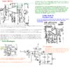
But it is confusing in terms because you look at the means to MODULATE the Regulated carrier (your AM regulator) so they use a pre-set voltage and mix that in with an AF signal - but the two are mixed at the BASE of the transistor - so we no have the AF and Bias on the base, but use the OUTPUT of the PASS Transistor as the power SOURCE for this to occur.
- Where this even gets more intriguing is WHERE you send the OUTPUT - of this small amp. It's sent to the Input side of a Darlington Amplifier (2 stage).
- In a way we use the FEEDBACK principle to provide the method of your Reactance - as the Bias and AF drive the Darlington Pair - the output of that Darlington amp rises and falls - DYNAMICALLY - in two ways, both in the DC realm, and in AF realm - at the same time.
So as Audio peaks affect the Darlington - it affects the power sourcing of the Mixing Transistor - but not the BASE region - it's sill has steady DC and the varying AF signal.
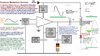
So the AM Regulator - can be defined as your "Reactance Modulator" as the device but the process occurs in the TX strip with the TX Mixer, Buffer and Pre-driver amps sending the Carrier RF signal to the Base of the Driver but we send this newly converted signal to the Collectors of the Driver and Final.
There are several AWESOME threads about this....
https://www.worldwidedx.com/threads/over-130-modulation.163831/page-4#post-458121
https://www.worldwidedx.com/threads/asymod.246057/#post-682941
You were even involved in this one too...
https://www.worldwidedx.com/threads/realistic-trc-427-audio-mod-goldfinger.237928/page-2#post-655208
So the thoughts are there, just the way Cobra, Uniden, Realistic and many others already used the "Tapped Power Choke" as the method to modulate the Collectors to a point where it's Class D and the Moniker "Plate Modulation" and Reactance Modulator somehow get thrown into this interchangeably.
So in a basic answer to your question - the 1/2 supply rail into a capacitor before it's applied to the Choke - we avoid the hassles of pre-existing conditions and support requirements of the Bias supply regulation used in an AM regulator and simply bring in the full voltage the Collectors need and let the power swings occur in the Modulation Transformer. The limitations are Phase effects, the distortion products of this conversion of treble tones and the roll-off from Hi- to Low within the Choke - altering the audio in both Phase and Frequency Bandwidth - narrowing Bandwidth and generating a Phase shift from this - and although we'd have FM or a good portion of it, we still have the envelope products of power peaking and toughing throughout the process - so we throw it thru a Diode and that changes the ballgame and help remove many of the opposing phase products and allows for the positive portions of this transformation process to pass into the collectors.
So again, the Modulation Transformer is only a Component of the process, we now introduced the Capacitor and Diode as the other two.


")