Hi all, I am working on a texas star 667v and am having trouble, I am getting 2 ohms from the bases to ground not 1.3 to 1.5. I have replaced all 3 of the half watt resistors though I had issues with them 2.7 coming out and reading at about 3.3 ohms, I even took 5 - 10 ohms and twisted them together then got my 2.7 reading however the ohm meter still read 2 ohms from the base of transistor to ground, what else could be faulty in this circuit to cause this issue ? Thanks

You are using an out of date browser. It may not display this or other websites correctly.
You should upgrade or use an alternative browser.
You should upgrade or use an alternative browser.
-
You can now help support WorldwideDX when you shop on Amazon at no additional cost to you! Simply follow this Shop on Amazon link first and a portion of any purchase is sent to WorldwideDX to help with site costs.
-
A Winner has been chosen for the 2026 July 4th Retevis RA89R Giveaway! Click Here to see who won!
Texas star 667v " bias issues"
- Thread starter Danzik
- Start date
Your ohm meter?Hi all, I am working on a texas star 667v and am having trouble, I am getting 2 ohms from the bases to ground not 1.3 to 1.5. I have replaced all 3 of the half watt resistors though I had issues with them 2.7 coming out and reading at about 3.3 ohms, I even took 5 - 10 ohms and twisted them together then got my 2.7 reading however the ohm meter still read 2 ohms from the base of transistor to ground, what else could be faulty in this circuit to cause this issue ? Thanks
Is this with bias resistors in or out of circuit? Measure B-E out of circuit?
Last edited:

I was just stating when some of those low ohm resistors I had bought like the 2.7 ohm didn't really measure exactly 2.7 when they were out of circuit so I thought that might have been the issue so I bought another batch of them of a different style and still got 3.3 ohm was supposed to be 2.7 so I put 5 - 10 ohms together and got my 2.7 ohms and installed but still continue to get 2 ohms or a bit more from the transformer base to ground, I hope this clears up my issue thank youYour ohm meter?
Is this with bias resistors in or out of circuit? Measure B-E out of circuit?
I'm not an amp guy, but I think your reading in circuit is lower because they are in parallel with the 10ohm resistors.
Could the higher value out of circuit be due to a wider tolerance? The difference of 0.6ohm / the marked value 2.7ohm = 22% error.
That 2.7ohm value has me curious. If you look down at the other half of the amp in that schematic, R23 is a 1.8ohm resistor. Not sure why R16 shows 2.7ohm, but the DX500v schematic show 1.8ohm for both. Not sure 2.7 is correct, that might be a typo. thanks for pointing that out to me xracer13
Could the higher value out of circuit be due to a wider tolerance? The difference of 0.6ohm / the marked value 2.7ohm = 22% error.
Last edited:
2.7ohm is the correct resistor for a 667 up front as it also feeds bias voltage to the driver. The 2.7 and 1.8 ohm resistors need to be metal film 1% tolerance.That 2.7ohm value has me curious.
The measurement is taken at the input side of the input transformer thats fed by the ferrite beaded wire that brings in the bias voltage from the bias circuit. 1.5-1.6 ohms is the usual reading.
Last edited:
Hi Xracer13, the newer resistors I got were metal 1%, the blue colored ones, but ended up getting the same reading of 3.3 ohms even with those I believe and tried a different multimeter with the same results, but yeah getting 2 ohms or slightly more on both boards off that input transformer to ground, will get back with more info later. I had recently restored a sweet sixteen with no problems and had good readings in these locations, not so much with this 667v2.7ohm is the correct resistor for a 667 up front as it also feeds bias voltage to the driver. The 2.7 and 1.8 ohm resistors need to be metal film 1% tolerance.
The measurement is taken at the input side of the input transformer thats fed by the ferrite beaded wire that brings in the bias voltage from the bias circuit. 1.5-1.6 ohms is the usual reading.
The reading from the resistors at 3.3 ohms was taken out of circuitI'm not an amp guy, but I think your reading in circuit is lower because they are in parallel with the 10ohm resistors.
Could the higher value out of circuit be due to a wider tolerance? The difference of 0.6ohm / the marked value 2.7ohm = 22% error.
That 2.7ohm value has me curious. If you look down at the other half of the amp in that schematic, R23 is a 1.8ohm resistor. Not sure why R16 shows 2.7ohm, but the DX500v schematic show 1.8ohm for both. Not sure 2.7 is correct, that might be a typo.thanks for pointing that out to me xracer13
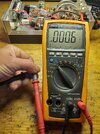
I will double check this just because and get back with you however I did try 2 different meters with the same resultsHere is a shot in the dark. What does the meter read when touching the probes together? If not 0.00 then you will need to subtract the added resistance of your probes (what the meter reads when touching probes) from that base-ground measurement.
No, once all the resistors are in circuit the measurement is taken from the input transformer or " transistor bases" to ground and then should come up with a reading of 1.5 ohm or Slightly less. I am kinda confusing some here because I checked my new bias resistors before I installed them and had a higher reading then I would like to see before hand and thought that might be the initial problem, but I no longer believe that. Thank you bunches for your help and reply it's appreciatedI'm not an amp guy, but I think your reading in circuit is lower because they are in parallel with the 10ohm resistors.
Could the higher value out of circuit be due to a wider tolerance? The difference of 0.6ohm / the marked value 2.7ohm = 22% error.
That 2.7ohm value has me curious. If you look down at the other half of the amp in that schematic, R23 is a 1.8ohm resistor. Not sure why R16 shows 2.7ohm, but the DX500v schematic show 1.8ohm for both. Not sure 2.7 is correct, that might be a typo.thanks for pointing that out to me xracer13
I don't know what meter your using but on my fluke 87III you can touch the test leads together and then push the REL delta button to zero out the leads. Then for measuring low ohm resistors you can hold down the peak min max button and that adds another number past the decimal or else the meter does average to the next number up or down with only one number past the decimal point..
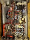
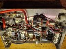
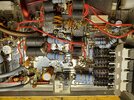
Can you post a pic of the amp with the camera facing straight down
Can you post a pic of the amp with the camera facing straight down
Last edited:
Yes sir, I will post a pic of the amp later tonight, and yes I need to invest in a fluke but it seems for the most part the cheapo meter I have has been pretty accurate as I just got finished doing the same procedure to a sweet sixteen and had no issues and came up with correct readings I don't know what meter your using but on my fluke 87III you can touch the test leads together and then push the REL delta button to zero out the leads. Then for measuring low ohm resistors you can hold down the peak min max button and that adds another number past the decimal or else the meter does average to the next number up or down with only one number past the decimal point..
Can you post a pic of the amp with the camera facing straight down
 thank you
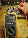
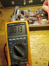
Pics per request and yes my multimeter read up to 000.8 ohm with the prongs together and I know the resistors are not to be doubled up like they are, I am just testing this to see if I could get better readings. It didn't test as bad today as I thought it did before but I bet it will go back after I replace these resistors but possibly it's just the multimeter is off ! However last time I put power to the unit the 10 ohms turned into candles and blew 2 brand new HG's so now I am scared lol !
Attachments
dxChat
- No one is chatting at the moment.
